VOGONS


First post, by elianda

User metadata
Rank l33t
Rank
l33t

Hello,

I mentioned it already in a few threads that I made a tool for use with the Epiphan grabber cards like VGA2PCIe and DVI2PCIe to automatically align the image, get the optimal dynamic and also measure the 2D image quality. The tool has now reached a beta state where it would be nice to have some feedback from other users since I can not test every situation myself.

The tool uses the SDK from Epiphan that is based on Java. You can get it here: ftp://ftp.retronn.de/align_tool/
(I have not tested it in Linux)

Requirements:
- Some more or less current Java JRE
- An epiphan capture card like VGA2PCIe or DVI2PCIe
- A computer that delivers a signal to the analog input and is able to show one of the test images (the BMP files in the same folder).

Limitations:
- The program does not support resolution changes after it initialized, it may crash or results will be meaningless (So if you change to another mode, restart it)

How to run:
Start run.bat.
By default it uses the first epiphan capture card, but you can give explicitly the serial number as parameter like 'run V2P80733' to use a specific card.

On the signal giving PC show the test image according to the resolution set in fullscreen and move the mouse to the lower corner.
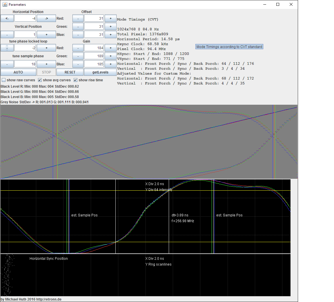
Now you can manually change the capture cards parameter or press the AUTO button. It will grey out as long as the alignment routine runs. You will see whats happening live.
You can move the image also when clicking on the preview window and use the cursor keys.

AUTO works only well if the value for phase locked loop is correct. Usually 0 is good. In some cases the area with the vertical black/white lines shows a horizontal moiree. Then tune the PLL value until the moiree is gone. That is not automatic yet. In the lower graph there should be the two dotted lines separated afterwards with one in the upper area and one in the lower. When PLL is right, run AUTO again.
The black level is set such way that the noise is below the lower limit. This gives a clean black for captures. It also means that it seems that the profile over the grey gradient seems to start late (i.e. not exactly in lower left corner). You can change this by tuning the Offsets.

Measuring the image quality:
Once the image is aligned, change the PLL by -2 or -3 so that the dotted lines show exactly two intersection points. (See also Screenshots in the folder)
The second graph will show then the signal for the width of two pixels. I show this for multiple scanlines so you see also some noise. Soft Trigger level is 50% grey (i.e. where the intersection points are).
The third graph shows with the black pixels the stability of the horizontal sync edge with the same x-scale as the graph above (the 1000 pixels shown in the graph represent 2 pixel width of the captured signal).
The x-scale of the third graph is only valid when there are exactly two intersection points for the dotted lines visible.
Notes:
- The signal curve does usually not reach full white or black since alternating white/black lines are the worst case. So for a single white pixel between two black pixels no card will reach the same white level as for a white area. But worst case is good for judging the output.
- All graphs are separated in R,G,B.

You can see in the screenshots how the signal gets worse with higher resolutions with the S3 Trio3D.

So any feedback?

There is also a brief video that shows the program in action: https://www.youtube.com/watch?v=f_u3Ot0paX4

Retronn.de - Vintage Hardware Gallery, Drivers, Guides, Videos. Now with file search
Youtube Channel
FTP Server - Driver Archive and more
DVI2PCIe alignment and 2D image quality measurement tool

Reply 1 of 32, by PhilsComputerLab

User metadata
Rank l33t++
Rank
l33t++

Thanks for the video! That did it for me and I tried in on a ATI Rage 128 Pro on my Windows 98 SE benchmarking station 😀

I captured the process, it works really well: https://youtu.be/tdX3A55VDOU

There is also some Quake II footage at the end.

I do have a few questions please:

- I had mine set to 32 bit colour, does this matter?

- "Once the image is aligned, change the PLL by -2 or -3 so that the dotted lines show exactly two intersection points." I didn't quite understand this, it seemed to mess up the image again. This isn't required for capturing?

The Quake 2 footage does seem quite dark. I lowered the offset to 30 for all channels and that removes the black crush. I think this is exactly what you mentioned regarding black levels.

EDIT: My manual calibration that I usually use is using a standard grey-scale and looking at two colour photos I know well. The manual setting were 30/170, so pretty close to what your tool set 😀

Possible suggestions:

- A RESET / STOP button of some sorts. If you forgot to full-screen the image, or close the tool while it's working and then come back, it is confused. You can get it working again by moving the sliders in the Epiphan tool and then going back to your alignment tool.

- Calibration images for other resolutions, especially 1600 x 1200 would be nice. I would also love to have one for PAL and NTSC resolutions so I can properly calibrate to the Mist FPGA computer. I should be able to display a full-screen image on the workbench? Though the colours will be limited...

YouTube, Facebook, Website

Reply 2 of 32, by elianda

User metadata
Rank l33t
Rank
l33t
PhilsComputerLab wrote:
Thanks for the video! That did it for me and I tried in on a ATI Rage 128 Pro on my Windows 98 SE benchmarking station :) […]
Show full quote

Thanks for the video! That did it for me and I tried in on a ATI Rage 128 Pro on my Windows 98 SE benchmarking station 😀

I captured the process, it works really well: https://youtu.be/tdX3A55VDOU

There is also some Quake II footage at the end.

I do have a few questions please:

- I had mine set to 32 bit colour, does this matter?

- "Once the image is aligned, change the PLL by -2 or -3 so that the dotted lines show exactly two intersection points." I didn't quite understand this, it seemed to mess up the image again. This isn't required for capturing?

The Quake 2 footage does seem quite dark. I lowered the offset to 30 for all channels and that removes the black crush. I think this is exactly what you mentioned regarding black levels.

EDIT: My manual calibration that I usually use is using a standard grey-scale and looking at two colour photos I know well. The manual setting were 30/170, so pretty close to what your tool set 😀

Possible suggestions:

- A RESET / STOP button of some sorts. If you forgot to full-screen the image, or close the tool while it's working and then come back, it is confused. You can get it working again by moving the sliders in the Epiphan tool and then going back to your alignment tool.

- Calibration images for other resolutions, especially 1600 x 1200 would be nice. I would also love to have one for PAL and NTSC resolutions so I can properly calibrate to the Mist FPGA computer. I should be able to display a full-screen image on the workbench? Though the colours will be limited...

Thanks for testing.

Color Depth: Does not matter, as long as you get the pure colors in the image. However this should even be the case with 256 colors. Actually with lower color depth you will see that the grey gradient turns into steps. Then you can even identify if the e.g. HiColor mode is 15 bit with 555 or 16 bit with 565. With 565 you have twice the color resolution on green which shows as smaller steps for green compared to red/blue.
Additionally required is that the white lines on top/bottom/left/right are visible for the position alignment.

PLL detuning: It is not required for the alignment. For the Alignment the PLL should be set to the correct value, which is 0 in your video (R/G/B dotted lines more or less straight on top and on bottom of graph)
The detuning is required if you want to see the signal profile over two pixels. You actually showed this in the video at about 0:40, where PLL was set to 2 and the dotted lines in the first graph had two intersections each. The additional vertical lines are just markers showing the intersection position. The second graph shows the scan over two pixels (black to white).
So the detuning is only required to see the High Resolution pixel scan. For capturing it has to be set back.
btw your Rage128 signal quality looks quite good compared to the screenshot of the S3Trio3D I uploaded.

Your alignment results:
Position is good, of course 0,0 is the trivial case but this just means that the sync signal has sharp edges and the cards timing follows the VGA specification.
Offset, yes the 32 crushes black a bit as with noise on black with captures you often get some structures from the noise after encoding in areas that should be black. I could change this of course that it stops earlier, where the line starts in the corner.
Gain: You see that you get for R 177, G 173 and B 176 and all lines from the gradient overlap perfectly. But this means that if you set one gain for all components then the lines will not overlap (You can try, just set 177 for all three). Then the whole image gets a color tint, especially visible on white / end of the grey gradient bar. You can not set different gains for each component with the epiphan tool. Also the exact values to get a real white are quite difficult to get manually by eye judging.
Alternating lines: It seems that the blue component is brighter on the white lines and darker on the black lines than the R/G component.
Noise: Standard Deviation on grey is the same for all three components.

So the Rage128 is already a rather new card with sharp signals, only RGB brightnesses are not so well balanced.

Stop/ Reset button ok. With reset you mean recover the values that had been set when the program was started?

Image for 1600x1200 - ok i will make one. The program uses percentage of the screen size for the different fields.

additional note: you can disable the text in irfanview fullscreen mode in options/viewing/ disable the lower checkbox for the textfield.

Retronn.de - Vintage Hardware Gallery, Drivers, Guides, Videos. Now with file search
Youtube Channel
FTP Server - Driver Archive and more
DVI2PCIe alignment and 2D image quality measurement tool

Reply 4 of 32, by elianda

User metadata
Rank l33t
Rank
l33t

Some Development Screenshot:
http://retronn.de/ftp/align_tool/Screenshot_2.png

Stop/Reset Buttons are added, Mode Timing Information and an actual Scale on the graphs. Yes the 1 ns per division is correct.

Retronn.de - Vintage Hardware Gallery, Drivers, Guides, Videos. Now with file search
Youtube Channel
FTP Server - Driver Archive and more
DVI2PCIe alignment and 2D image quality measurement tool

Reply 6 of 32, by elianda

User metadata
Rank l33t
Rank
l33t

The mode timing calculation is not just for Info, my actual idea is the following:
If I can calculate the mode timing values the same as the epiphan software uses for the standard modes then I can suggest from the HShisft/VShift of the aligned image values for a custom mode. This custom mode should have correct alignment compared to the standard timings from the standard mode.
So if one would add a mode with that timings and uncheck the mode from the standard ones it would directly sync aligned.

If one does that for all used modes of a graphics card it would be like a template where all modes sync perfectly.

So currently for regular modes my calculated timings are identical to epiphans, however for interlaced modes I am still looking into it since there appear differences.
There are variants for mode timing calculations and I dont know precisely which method Epiphan uses internally.
(Well my results for interlaced modes sync as well as custom mode, so they can't be too wrong)

The actual adjustment is probably just as easy as looking at HShift=VShift=0 at the offset of the vertical white border lines and apply that offset to the porches (Once having the same timing as the epiphan tool uses for shifts of 0/0).

Retronn.de - Vintage Hardware Gallery, Drivers, Guides, Videos. Now with file search
Youtube Channel
FTP Server - Driver Archive and more
DVI2PCIe alignment and 2D image quality measurement tool

Reply 7 of 32, by elianda

User metadata
Rank l33t
Rank
l33t

Another version is up:

Changes:
- Reset Button resets settings to the ones at program start
- Stop Button stops Auto Alignment run
- Mode Timing Output
- Scales on the lower graphs
- Mode Timing Suggestion output for Custom Mode Creation in Epiphan Tool.

How to get a aligned Custom Mode (with HShift/VShift = 0):
In the Epiphan Tool for a clean start:
Go to the VGA Modes tab, add a custom mode with default VESA Timings checked, like 800x600 at 60 Hz.
Uncheck Standard VGA Modes and all other modes in Custom Modes.
Uncheck the just created mode once, apply -> looses Sync as no mode exists
Check the created mode again to trigger a resync with the default VESA timings.

Run the alignment tool, once aligned it shows in the Mode Timings Output at the bottom two lines as Adjusted Values for Custom Mode.

Go back to the Epiphan Tool, set HShift and VShift to 0.
Go to the VGA modes tab and edit the created Custom mode, uncheck 'Standard VESA Timings'.
Enter the Timing Values from 'Adjusted Values for Custom Mode' in the Alignment tool.
Press Ok, Uncheck and Recheck the custom mode again that it looses sync and force a resync.

If the original mode was interlaced then the alignment tool will output another line called 'Epiphan Interlaced Hack' for the Vertical Timing Values.
In this case use these values for the Vertical Timing. (Horizontal still from the 'Adjusted Values for Custom Mode' part).

What is currently impossible for me:
If different modes require a different PLL setting it can not be set for the custom mode. You can only tune the Actual Vertical Frequency.

Retronn.de - Vintage Hardware Gallery, Drivers, Guides, Videos. Now with file search
Youtube Channel
FTP Server - Driver Archive and more
DVI2PCIe alignment and 2D image quality measurement tool

Reply 9 of 32, by elianda

User metadata
Rank l33t
Rank
l33t

So I added a series of screenshots from the S3, an old ET4000 (80 MHz DAC) and Matrox Millenium to show that it really shows the differences. I used the original short shielded VGA cable for that came with the DVI2PCIe.

I thought about the following:
If I set thresholds of 85% black and 85% white I can get the time the signal takes to go from one level to the other. (In the Screenshots it is in the range of ~10 ns to ~8 ns). The inverted time would a frequency which number gets higher the steeper the signal rises (the shorter the time interval is). This may give a nice number for comparison.

Another thing is that for a set sample phase it is not exactly clear where the capture card actually samples on a pixel. However I know the white/black level in the area of the alternating lines for PLL = 0. So I can look in the curves with PLL = -2 where the curve reaches those levels. And these two points must have exactly one pixel distance (half of the x-range). So I can pinpoint the location on signal where the card takes a sample.

Would this be interesting?

Retronn.de - Vintage Hardware Gallery, Drivers, Guides, Videos. Now with file search
Youtube Channel
FTP Server - Driver Archive and more
DVI2PCIe alignment and 2D image quality measurement tool

Reply 10 of 32, by PhilsComputerLab

User metadata
Rank l33t++
Rank
l33t++

I can only speak for me, but I'm truly happy with what the tool does at this point already 😀

I'm not sure I would use the other features to be honest.

Can I just resize the 1024 x 768 image to other resolutions, or how do you create these images?

YouTube, Facebook, Website

Reply 11 of 32, by elianda

User metadata
Rank l33t
Rank
l33t

I use in the program percentages relative to the resolution for the areas.

If you want test images in other resolutions the following workflow is practical:

Load one of the test images preferred the one with the highest resolution.
Resize to the new resolution using nearest neighbor point interpolation. (pixel doubling) - this keeps the relative percentage size of the areas
Redraw the lines at the edges at the left/right/top/bottom as single pixel lines.
mark the gray gradient area and refill with a new gradient from black to white in horizontal direction.
Now the alternating lines: Start at the left with a black and a white line each one pixel in thickness. Mark an copy it then to the left a few times. Flatten the layers and you can mark a larger area to copy to the left again. Do this until you have alternating lines in the whole width.

Retronn.de - Vintage Hardware Gallery, Drivers, Guides, Videos. Now with file search
Youtube Channel
FTP Server - Driver Archive and more
DVI2PCIe alignment and 2D image quality measurement tool

Reply 12 of 32, by PhilsComputerLab

User metadata
Rank l33t++
Rank
l33t++
elianda wrote:
I use in the program percentages relative to the resolution for the areas. […]
Show full quote

I use in the program percentages relative to the resolution for the areas.

If you want test images in other resolutions the following workflow is practical:

Load one of the test images preferred the one with the highest resolution.
Resize to the new resolution using nearest neighbor point interpolation. (pixel doubling) - this keeps the relative percentage size of the areas
Redraw the lines at the edges at the left/right/top/bottom as single pixel lines.
mark the gray gradient area and refill with a new gradient from black to white in horizontal direction.
Now the alternating lines: Start at the left with a black and a white line each one pixel in thickness. Mark an copy it then to the left a few times. Flatten the layers and you can mark a larger area to copy to the left again. Do this until you have alternating lines in the whole width.

Got it, thanks! Will have a go at this 😀

YouTube, Facebook, Website

Reply 13 of 32, by elianda

User metadata
Rank l33t
Rank
l33t

Actually this is also one thing I had some thoughts about:

I can add a button that overlays markings for the areas used on the main image. So one could check if the patterns are at the correct locations.
And I could also change it that it reads the percentage values from a text file.

Retronn.de - Vintage Hardware Gallery, Drivers, Guides, Videos. Now with file search
Youtube Channel
FTP Server - Driver Archive and more
DVI2PCIe alignment and 2D image quality measurement tool

Reply 14 of 32, by elianda

User metadata
Rank l33t
Rank
l33t

So are a few new features (description below):

align_tool_screenshot.png

Example image is from a Matrox Millenium

- added checkboxes to select what is shown.
- Shows now the averaged curve.
- show rise times gets the time where the signal rises from 15% to 85% intensity. It shows the corresponding frequency as well. The shown 257 MHz are higher than the DAC frequency of the Matrox Millenium (220 MHz), but it is only 15 to 85% and not e.g. 5% to 95% which would be much slower. The yellow horizontal lines show the 15%/85% levels.
- shows estimated sample position. This is where the ADC is most likely taking the sample on the pixel for the sample phase setting. To get this enabled, change PLL to 0 (or where it is not detuned) and push 'getLevels'. Then change back to -2. The white line is the average of the RGB lines. I would assume the three DACs for RGB sample at the same time.

Retronn.de - Vintage Hardware Gallery, Drivers, Guides, Videos. Now with file search
Youtube Channel
FTP Server - Driver Archive and more
DVI2PCIe alignment and 2D image quality measurement tool

Reply 15 of 32, by elianda

User metadata
Rank l33t
Rank
l33t

I made a page with documentation http://retronn.de/imports/dvi2pcie_align_tool.html

Retronn.de - Vintage Hardware Gallery, Drivers, Guides, Videos. Now with file search
Youtube Channel
FTP Server - Driver Archive and more
DVI2PCIe alignment and 2D image quality measurement tool

Reply 17 of 32, by PhilsComputerLab

User metadata
Rank l33t++
Rank
l33t++

Elianda, I got a request please.

Is it possible to implement a tick box, or toggle button that sets the black level to standard levels, at the cost of noise? I keep forgetting to change the gain manually and I have to re-do captures 😊

YouTube, Facebook, Website

Reply 18 of 32, by elianda

User metadata
Rank l33t
Rank
l33t

Ok, there have been a few more comments lately, like more robustness in the case the card looses sync when changing values.

Retronn.de - Vintage Hardware Gallery, Drivers, Guides, Videos. Now with file search
Youtube Channel
FTP Server - Driver Archive and more
DVI2PCIe alignment and 2D image quality measurement tool

Reply 19 of 32, by elianda

User metadata
Rank l33t
Rank
l33t

Ok new version is up.
It should also be more stable versus lost signal.

Retronn.de - Vintage Hardware Gallery, Drivers, Guides, Videos. Now with file search
Youtube Channel
FTP Server - Driver Archive and more
DVI2PCIe alignment and 2D image quality measurement tool