Reply 460 of 496, by snipe3687

- Rank
- Newbie
Eivind wrote on 2024-05-13, 13:14:That's great to hear! 🎉 […]
snipe3687 wrote on 2024-05-13, 12:19:Quick update on the other minor issue with the static, yeah I'm a dummy sometimes, I put to caps on 90 degrees from where they should be and rotating them back to where they're supposed to be fixed that issue.
That's great to hear! 🎉
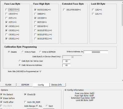
snipe3687 wrote on 2024-05-13, 12:19:I flashed it the way you mentioned above a few days ago and it seems to have flashed correctly but when I connect a USB mouse to the port it doesn't do anything in windows.
I'd start by connecting only a single USB keyboard to one of the HID ports and take it from there. Mice (and hubs) are generally trickier and there _can_ be incompatibilities.
If you want to try to debug the rp2040, there's the TTL serial (115200 bps, 8N1) J46 connector you can hook up to look at output from the firmware. You'd have to enable debug output in code and recompile another firmware first though.
ah...yeah I don't really know how to do that. I'm leaning toward, I probably messed up something when I compiled. I don't suppose you could send me a compiled UF2 file that is known working could ya?