VOGONS


My first pc - restoring

Topic actions

Reply 40 of 87, by tayyare

User metadata
Rank Oldbie
Rank
Oldbie

Some motherboards were also supporting keyboard switching. "ctrl" + "alt" + "+" and "ctrl" + "alt" + "-" if I remember correctly.

GA-6VTXE PIII 1.4+512MB
Geforce4 Ti 4200 64MB
Diamond Monster 3D 12MB SLI
SB AWE64 PNP+32MB
120GB IDE Samsung/80GB IDE Seagate/146GB SCSI Compaq/73GB SCSI IBM
Adaptec AHA29160
3com 3C905B-TX
Gotek+CF Reader
MSDOS 6.22+Win 3.11/95 OSR2.1/98SE/ME/2000

Reply 41 of 87, by alexanrs

User metadata
Rank l33t
Rank
l33t

Only two pins of the three pin connector are necessary IF those mystery pins are for a turbo header. The middle one is common - it should always be connected to the header - and the two outer ones define how the button works. One pin shorts with the middle one when the button is pressed, and the other when it is released. That way you can choose how the button works (full speed = pressed button or full speed = released button).

Reply 42 of 87, by ramiro77

User metadata
Rank Member
Rank
Member

Alright. It was maybe connected with only two pins. I have yo try it. Also I will try keyboard switching. Is there any software that I could use to check if turbo is working? Perhaps something like cpuid?

Reply 43 of 87, by alexanrs

User metadata
Rank l33t
Rank
l33t

There is no standard way to check it. And every motherboard implements turbo in a diferente way: some might drop the FSB, some might add wait states, some might just disable caches, and so on.

Reply 46 of 87, by TELVM

User metadata
Rank Oldbie
Rank
Oldbie
ramiro77 wrote:
Well. It's done :cool: I went from something like this (illustrative image): […]
Show full quote

Well. It's done 😎
I went from something like this (illustrative image):

HS40Eb.jpg

to this:

otnrlu.jpg

hwwi00.jpg

It took me something like four hours. I didn't use caustic soda, just a lot of sanding. I kept some black anodized finish between fins. Now I have to buy a 40 milimeter fan to put in there. I tested it with a noisy damaged one and the heatsink remains cold in almost every condition.
Today I also did some wire soldering in the front panel. I can't find pin connectors for the motherboard in every store I ask for it. It's a little weird, I bought a bunch of them some months ago.

Good work, nice DIY initiative and skills! respect-048.gif respect-048.gif respect-048.gif

Another option might be to replace the voltage regulator with one of these gadgets, they're about 90% efficient and thus dissipate little heat.

TSR%2B1-2450.jpg

TracoPower TSR-1

Implementation on a venerable ZX Spectrum +, allowing removal of heatsink: http://blog.tynemouthsoftware.co.uk/2014/11/z … -regulator.html

Let the air flow!

Reply 47 of 87, by alexanrs

User metadata
Rank l33t
Rank
l33t

Beware that it is a step-down regulator, and might have higher ripple than the regulating system already there, so you might need to improve the output filtering.

Reply 49 of 87, by ramiro77

User metadata
Rank Member
Rank
Member

Don't bother guys. I can't get those in my country. In fact this is the first time I see that. 😢
The motherboard is working really well with my diy heatsink plus a little fan blower. I only have to buy a new fan and that chapter is done 😎

Reply 50 of 87, by k0vnas

User metadata
Rank Newbie
Rank
Newbie
TELVM wrote:
Yep that voltage regulator would be happier with a real heatsink. […]
Show full quote

Yep that voltage regulator would be happier with a real heatsink.

file.php?id=21283&t=1

This looks just like the one on my FIC PA-2005. With Pentium MMX it can run quite hot, and I wonder if maybe I should put a 486 fan nearby. Manual only suggests to pay attention to the direction of the airflow from CPU fan in case of Cyrix 6x86 though.

As for the turbo - on many motherboards it's possible to connect the switch to one multiplier jumper. From my experience - the turbo button on Pentiums usually disables CPU cache.

Reply 52 of 87, by ramiro77

User metadata
Rank Member
Rank
Member

I found motherboard connectors! Finally!
Also I found 2x16mb edo for my mother, although it only recognize 2x8mb because density of sticks.

Now I'm stuck at one very weird issue. IDE activity led and reset pins doesn't work at all. I've tried with several leds and switches and nothing, and I tested all the leds and switches and they are fine. Besides that, yellow power led isn't bright at all. It's only visible at full darkness. I'm starting to think that there is something wrong with my motherboard. 😢

EDIT: nevermind. Serigraphy was wrong labelled. I installed connectors by trial and error and now it's all fine. I'll post pics later.

Reply 53 of 87, by ramiro77

User metadata
Rank Member
Rank
Member

Major update. Things done:

- Linear voltage regulator cooling: I bought a new 40 milimeters fan blower. It's dead silent at 5v and barely audible at 12v. It keeps the heatsink frozen and allows some airflow. I did the wiring myself of course.

1zqsz9h.jpg

beh8oo.jpg

- Turbo led display configuration: By trial and error. It took me one hour.

2quka36.jpg

vyvcwz.jpg

- Case leds: By trial and error. Serigraphy was wrong labelled on my motherboard.

6hnegz.jpg

And I've found something really cool. A source for Maxi Sound NOS keyboards at ridiculously symbolic price. I bought two for me and one for a friend at less than four dollars each. They are brand new in sealed packaging. Yay! They have grey/white combination! My favourite!!! 😎 😎 😎

20plow.jpg

4g5so.jpg

wqu9vr.jpg

nnsh05.jpg

Now I'm struggling with anoooooother issue. Originally I had 2x8 mb EDO simm modules (double sided, six chips total) in bank 0 working perfectly. The first time I added the 2x16mb EDO simm modules (single sided, 8 chips total) in bank 1, my motherboard recognized them as 8mb each but it worked only one time. When I rebooted, the bios started to promp "memory test fail" message. If I switch banks, the system doesn't even boot. But if I put the 2x16mb modules in bank 0, my motherboard recognizes the full amount. Another weird issue. Any thoughts on this?

Last edited by ramiro77 on 2016-01-06, 02:04. Edited 1 time in total.

Reply 54 of 87, by Tetrium

User metadata
Rank l33t++
Rank
l33t++
ramiro77 wrote:

Now I'm struggling with anoooooother issue. Originally I had 2x8 mb EDO simm modules (double sided, six chips total) in bank 0 working perfectly. The first time I added the 2x16mb EDO simm modules (single sided, 8 chips total) in bank 1, my motherboard recognized them as 8mb each but it worked only one time. When I rebooted, the bios started to promp "memory test fail" message. If I switch banks, the system doesn't even boot. But if I put the 2x16mb modules in bank 0, my motherboard recognizes the full amount. Another weird issue. Any thoughts on this?

Perhaps you're trying to mix parity with non-parity modules?

Whats missing in your collections?
My retro rigs (old topic)
Interesting Vogons threads (links to Vogonswiki)
Report spammers here!

Reply 55 of 87, by ramiro77

User metadata
Rank Member
Rank
Member

Mmm I don't know. Do you mean ECC modules? If so, I don't think they are ECC because they were installed on a regular k6 motherboard. The label doesn't say anything about ECC. This is strange to me because my motherboard was never picky at ram modules. It even supports an impair number of simms as long as the bank 0 is filled.

I will see if I can find more simms and try. 32mb isn't what I want. At least I want 48mb, that would be enough for gaming. But this is a pity because it means that I can't use the original 2x8mb modules, and I wanted to do that.

Reply 56 of 87, by Tetrium

User metadata
Rank l33t++
Rank
l33t++
ramiro77 wrote:

Mmm I don't know. Do you mean ECC modules? If so, I don't think they are ECC because they were installed on a regular k6 motherboard. The label doesn't say anything about ECC. This is strange to me because my motherboard was never picky at ram modules. It even supports an impair number of simms as long as the bank 0 is filled.

I will see if I can find more simms and try. 32mb isn't what I want. At least I want 48mb, that would be enough for gaming. But this is a pity because it means that I can't use the original 2x8mb modules, and I wanted to do that.

Memory modules which have a number of chips that's not equal to a number that is a power of 2, usually are parity (mostly SIMMs) or ECC (mostly DIMMs).
Iirc mixing these types of modules could result in problems which would usually not result in permanent hardware damage, but not all boards supported parity modules and some board wouldn't run without parity modules.

Some could perhaps run both, but not at the same time.

Whats the total number of chips on your memory modules?

Whats missing in your collections?
My retro rigs (old topic)
Interesting Vogons threads (links to Vogonswiki)
Report spammers here!

Reply 58 of 87, by ramiro77

User metadata
Rank Member
Rank
Member

Well, I have good news. I had tried several combinations without luck until I found total hardware 99. I saw memory bank arrangement for my motherboard. I was wrong, I thought that the two first slots were bank 0 and the other two were bank 1, but no, they are mixed (first bank 0 simm 1, then bank 1 sim 2, then bank 0 simm 3 and the last one is bank 1 simm 4). So I tried the two last possible combinations. With first combination it doesn't boot. With the last possible combination...

iqymmt.jpg

BINGOOO!!!!!! They are arranged like this:

2rorzw9.jpg

Bank 0: 8mb 6 chip modules.
Bank 1: 16mb 8 chip modules.

Now I have the furious amount of 48mb of EDO ram using my original 2x8mb sticks 😎
So I can conclude that I'm a little bit idiot and I have to read better the manuals/datasheet before doing things that I don't remember. This system is almost 21 years old and of course there are many things that I forgotten.

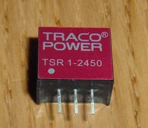
Another subject: we have 220 volts outlets here, while you have 110 volts. Maxisound's keyboards came with 110v power supplies for the amplifiers. Lets suposse that I buy a 220v transformer: the keyboard doesn't have any switch to turn off the amplifiers. I didn't like the idea of leaving it turned on, so I did this:

m0w35.jpg

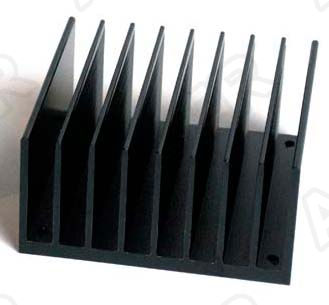
I drilled a hole in a bracket and screwed a connector. It's soldered to a molex (5v). I used the 12v connection to power the fan blower attached to the regulator. Resuming: one molex for two purposes. It's really neat.

I will come in next days with more updates. See you! 😎

Reply 59 of 87, by ramiro77

User metadata
Rank Member
Rank
Member

Well guys, this is coming to the end. I bought a second hard drive for backup data. It's a 1700mb Seagate 4500rpm with a removable caddy. I didn't like the idea of keeping the unit turned on forever, so I did some modding to it.
I added this double switch:

spf5fc.jpg

16bylpw.jpg

It's a NOS switch from our (now dead) national industry. It has a little filament light bulb in there. I didn't use the bulb because it's too much, but it's a nice feature. Now I can turn off the drive when I don't use it.

ve3r48.jpg

i2qf6p.jpg

And finally closed:

6th0ld.jpg

Final specs (by now):

- Motherboard FIC PA-2001 socket 7 with 256kb cache
- Pentium 200 mhz MMX
- 48mb edo ram
- Trident 9680 1mb PCI
- Addonics sound vision 500 (Yamaha OPL3-SA)
- USB PCI card
- NOS Genius 50x CD-ROM drive
- Floppy 1.44mb
- Samsung 4.3gb as primary hard drive
- Seagate 1.7gb as secondary backup drive
- Maxi Sound keyboard with Altec Lansing integrated speakers
- Philips 109e5 19 inches CRT monitor
- Windows 95 OSR2.1 spanish (trying to install USB drivers. If USB doesn't work, I will come back to w98se).

Next chapter will be implementing some turbo function and upgrading VGA. Sadly, I bought a Diamond Viper V330 8mb PCI which is damaged. I'm still wating for refund.