First post, by DonutKing

- Rank
- Oldbie
Hello peeps 😀 I've recently finished building a 286 system, and in this thread I'll be describing the parts and the build process. It was quite a learning process for me since I didn't get into PC's until the early 90's. This system dates from the late 80's and a lot of things are quite different. Compared to a PC of today, the systems physically have very little in common.
After building a 386 and 486 I wanted to go back a little further and explore technology from the previous decade. The 80's was a pretty big era for computing, and the computer marketplace was vastly different from today, with companies like Commodore, Sinclair, Apple, Atari, Tandy and so on selling their own designs of microcomputers, and they were generally incompatible with each other. (some were sold in a kit form that you had to assemble yourself, often with no monitor- you'd plug your own TV into it). Commodore dominated the marketplace with the C64 for several years and their Amiga computer was very advanced for its time- originally released in 1985, the Amiga had graphics and sound capabilities that wouldn't be matched by IBM PC's (or their clones) for several years. I hope to go further back and fiddle with some of these older machines, should the opportunity arise, but for now this is a good starting point.
This machine is basically an IBM-compatible clone, loosely based on the specs of a mid range 1988ish machine. It could be considered a 'turbo AT' type clone machine. Google Books have some archived copies of InfoWorld and looking at a few issues from 1988 it seems a similar specced machine could be bought for about $1500-1800 USD.
So, to start off with I needed a case. I was lucky to pick this one up from OCAU:
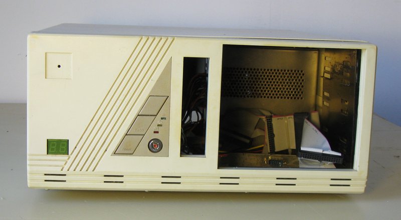
It had been unloved in a shed for a number of years, so I stripped it down and gave it a good clean out.
A very retro style case, its got all the oldschool features like a turbo button and LED speed display. Very solid thick steel construction too. Its lid opens up on a hinge on the back of the case, and has a latch to keep the lid propped up - like the hood of a car. You'll notice that its missing a case badge. I've ordered a case badge printer kit and just waiting for it to arrive so I can make one, any suggestions for an appropriate badge will be appreciated 😀
It included a 200 watt power supply, and a quick test with a multimeter and a couple of fans confirmed that it still worked. Of course it was full of crud from sitting in a shed so I opened it up and gave it a good cleanout too. No bulging capacitors or anything else obviously wrong.
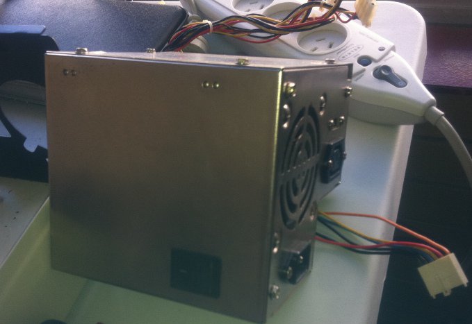
Its quite different from power supplies today. It's physically bigger and has a right-angle shape, unlike the rectangular shape of modern power supplies. The mounting screws are all in the same place so you could fit a rectangular power supply in the case without much effort. The connectors haven't changed much, the familiar Molex and Berg connectors for disk drives are all there. There are 3 Molex connectors and one Berg, and two connectors for the motherboard.
Notice that black shape on the side facing the camera. That is the system power switch. Back in these days, power switches were located on the back or side of the case, rather than on the front. The front of the case has reset and turbo buttons, but to physically turn the system on or off you have to reach around the right side of the system and flick this big switch. There's a small cutout in the side of the case for this switch to poke through. The cutout is visible in the top right of this photo:
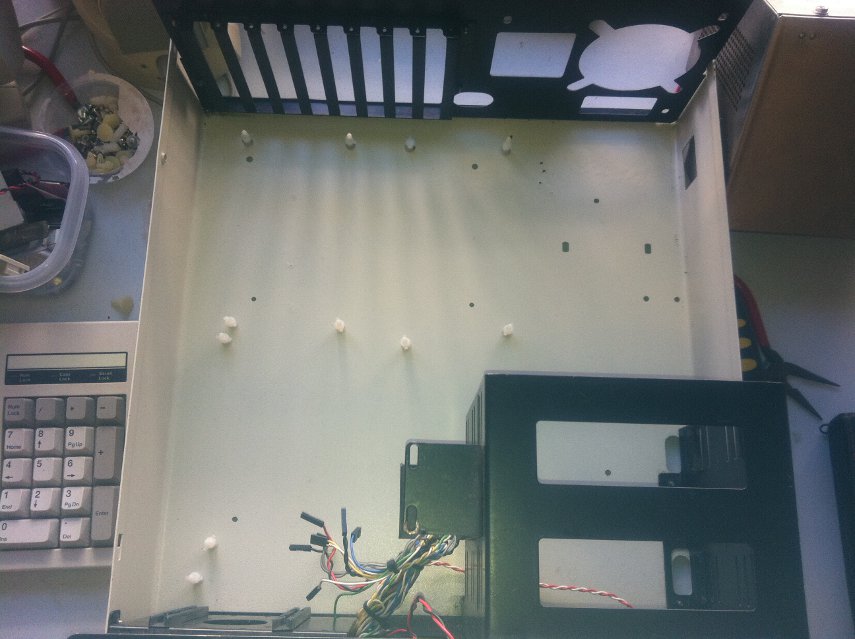
Here you can see what caused the biggest holdup in the whole project. Notice how the bottom of the case is completely flat? There is no motherboard mounting tray. Modern PC's have a tray with threaded holes for you to screw metal standoffs into, and in turn screw the motherboard into the top of the standoff to secure it. Older machines often had slots in the tray so you could use a plastic riser with a small knob on the end, and slide it into place to secure the board. This case had neither. The holes in the bottom of the case were not threaded and even if they were, they are too big for any standard risers or standoffs. I went to the local hardware store and bought some metal nuts and washers. The idea was that I could screw into them from underneath the case, and use a washer to reduce the size of the hole. However this placed the motherboard too low in the case. Expansion cards would bolt into the rear bracket securely, but their connector would not actually reach the motherboard's ISA slot.
So I went to Jaycar and bought some 10mm plastic PCB risers, with a threaded hole in the end. Unfortunately the first plastic risers I used were 10mm and they raised the motherboard too high- it was impossible to secure any expansion cards because they raised up above the bracket.
I ended up having to order some 5mm risers, and once screwed in from underneath the case, they turned out to be just about the right height.
So with that taken care of, let's have a look at the motherboard.
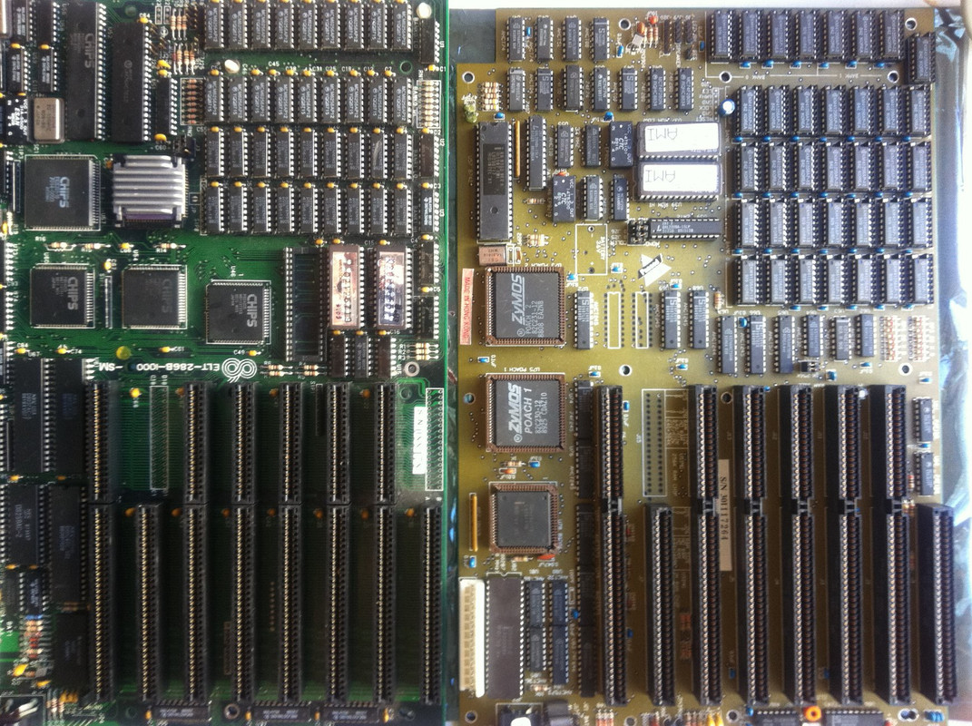
I actually have two 286 motherboards. The one on the left is the one I ended up using, its a 10MHz 286 board, with a Chips and Technologies chipset. The other board runs at 12MHz and has a ZyMOS POACH1 chipset. The 10MHz board appears to have been manufactured sometime in 1988 judging by the dates on its components, while the 12MHz board was made a year later.
Notice the two ZYMOS chips are socketed; back in these days it was cheaper to repair motherboards rather than just throw them out. Of course, today's motherboards complexity and pin count has increased by such an order of magnitude that it is very difficult to repair them, generally making it uneconomical for anything more complex than a blown capacitor or similar.
Speaking of capacitors, the yellow and blue dots you see everywhere are tantalum bead capacitors. Most modern boards use the tin can style electrolytic capacitors. The tantalum's are no less prone to failure though, as I discovered while peering over the 12MHz board when an arc of electricity flared up just inches from my face. I managed to replace the cap and it still worked afterwards.
The CPU on the left is under the metal heatsink and on the right board, its just below the two ZyMOS chips. It appears someone attached this board at some stage trying to get the CPU out of it (notice the corners of the socket appear damaged); it still worked but that combined with the blown cap made me decide to leave the 12MHz board as a spare for now.
Here's a closer look at the 10MHz CPU:
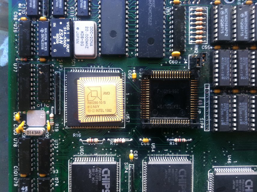
Yes, its an AMD 😀 Intel outsourced manufacturing to several other suppliers such as Siemens and Harris as well as producing their own chips. This is a Leaded Chip Carrier (LCC) form-factor CPU. Notice the lack of any pins on the CPU itself- Intel's LGA style sockets were hailed as revolutionary when they came out but you can see that the basic idea of a flat CPU with pins in the socket has been in use for a long time before that. Of course, LGA style chips have several hundred more pins so they are a much more complex design 😀
On the top right of each board are several rows of chips... this is the RAM. Today we are lucky that all the RAM comes on a couple of long sticks, back then you used DIP chips inserted into sockets on the motherboard like you see here. Upgrading a systems RAM is quite a tedious affair as you had to fully populate a bank of 18 chips at a time, being careful not to bend the delicate legs of each chip as you push them into their socket... or put a chip in backwards, or offset by one pin, and so on... Each chip has a dot or notch on top which corresponds to a notch in the socket, and Bad Things Happen if you overlook this detail.
Not only that, you have to set a jumper on the motherboard to tell it how much RAM is installed, AND you have to manually type in the amount of RAM in kilobytes into the BIOS setup.
To top it off... one of the memory chips was bad. The system would halt at POST with a "PARITY ERROR AT 00:8000:D7FF". It turned out to be just one chip, but finding it turned out to be a pain. The address suggested it was in the second bank of memory (since the value was over 512,000 bytes) but it still took a few goes to pick the faulty one out. Once it was swapped with a spare from the other board, the system booted without issue.
This particular system has a whopping 1 megabyte of memory. Each chip is 32 kilobytes. 1 megabyte is actually a pretty large amount for a system of this vintage as many were still being sold with 512KB. The 8088 used in the original IBM PC could only address 1MB of memory; the 286 could address up to 16MB however software had to be specifically written to take advantage of anything over 1MB. This was done by placing the CPU into what is known as 'protected mode'. Unfortunately the 286 didn't handle this very well (you needed a hardware reset of the CPU to switch back to standard 'real' mode from protected mode) which led to Bill Gates calling the 286 a 'brain dead chip'. Not much software was written to take advantage of protected mode on a 286. The 386 fixed a lot of the issues with protected mode and more software started to take advantage of it. But generally more than 1MB on a 286 is unnecessary as most software that needs more than that requires a 386 or greater.
In fact, the last 384KB of that 1MB is not normally accessable by most programs because of the 640kb barrier. In a nutshell, the first PC only had 64KB memory, and could be expanded to 256KB. Certain components of the system (like video cards, or hard disk controllers) needed a memory address for the CPU to access them, so IBM reserved the last 384kb of the 8088's 1MB address space for this purpose. As the years went on, and PC's started selling with more than 640kb of memory, and programs started being written to take advantage of this extra memory, this design desicion would be a thorn in the side of PC owners everywhere.
This limitation is fairly unique to the IBM PC architecture. The Amiga, for example, uses a Motorola 68000 series CPU which has 16MB of address space. At the time, most Amigas came with 512KB or 1MB of RAM. This left 15MB of address space that wasn't mapped to physical RAM. System components that needed address space to interface with the CPU could be mapped into this remaining 15MB, without interfering with system RAN and thus didn't cause a memory barrier.
One final thing to look at on the motherboard, is the 80287 Maths Coprocessor.
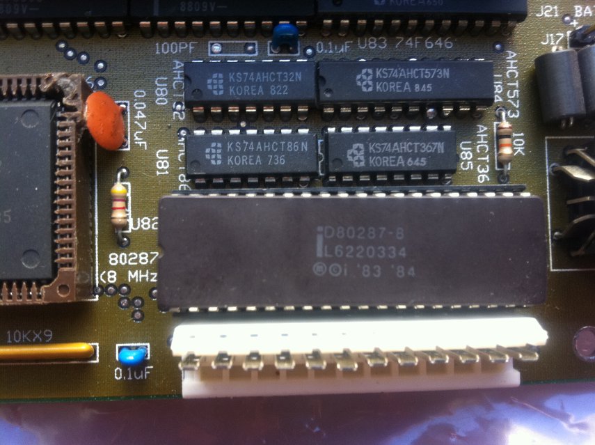
You can see it on the right side board near the white power connector. I pulled it out and used it in the 10MHz board.
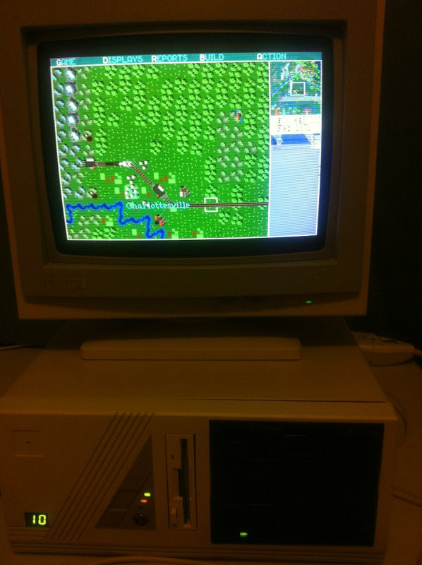
This chip takes care of advanced maths functions like floating-point arithmetic, trigonometry and so forth, which the 286 performs much more slowly. Applications needed to be specifically designed to take advantage of it; not many games did. The original Sim City does make use of it though, as the game advances through the years much faster with a co-pro installed.
You'll notice its only an 8MHz chip. 286 motherboards generally run the co-pro at 2/3 of the processor speed. So in the 10MHz system the co-pro is only running at 6.6MHz. This did reduce performance somewhat, so 386 systems ran the co-pro at the same speed as the processor, while 486DX and later systems integrated the co-pro's functions into the main CPU.
So enough chat. Time to put this beast together!
Its a bit of a tight fit as the board has to slide under the drive bays at the front of the case.
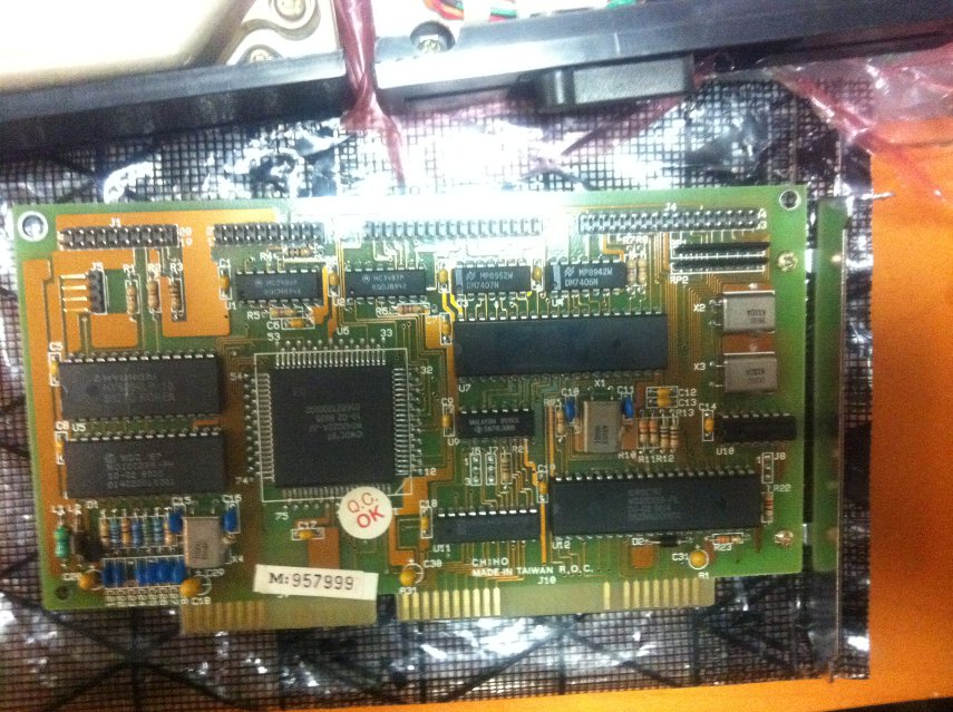
Next thing we need is a video card. Here we have an EGA video card with 256KB of onboard video RAM:
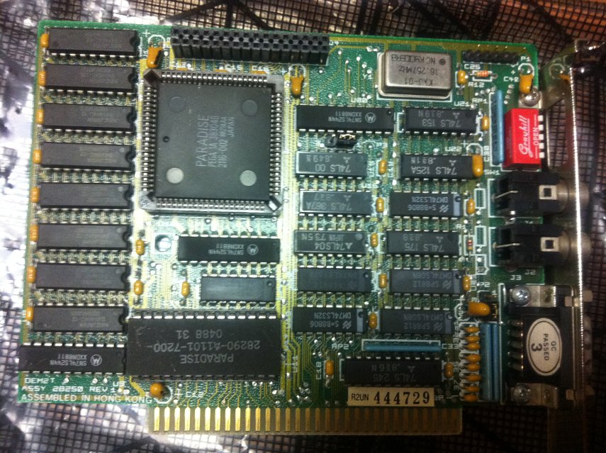
Its quite a bit different to modern cards. The familiar 15-pin VGA connector is nowhere to be seen. EGA, CGA and monochrome all used a 9-pin connector (just like a serial port). In addition, the earlier standards use a digital signal and VGA uses analogue. Modern machines using DVI output are using digital signals, isn't it interesting how technology comes full circle 😀 For this reason, VGA monitors are not compatible with earlier cards and vice versa.
Notice the two RCA jacks on the card. It is possible to hook up a composite monitor (such as a TV) to this card; computer monitors were quite expensive so a TV was an option for those on a budget. There is also a row of switches on the card bracket; since EGA is backwards compatible with CGA, monochrome etc, you can adjust these switches to suit your monitor. Unfortunately the default setting didn't pick up my EGA monitor so it took a bit of trial and error to get it set correctly.
Big thanks to RedHatter for kindly donating the EGA monitor 😀
EGA is an extension of the earlier CGA (which only allowed 4 colors on screen at once in graphics mode- out of a palette of 16 total colors. CGA Text-only modes allowed all 16 colors). EGA allowed 16 colors on screen at once in graphics modes, and expanded the palette to 64 colors. The default EGA palette was the same as the CGA palette, for compatibility reasons, so a lot of games stuck with these colors.
VGA expanded this to 256 colors on screen at once; from a palette of over 260,000. VGA was released in 1987 on the IBM PS/2, and clone VGA cards and monitors came on the market pretty quickly. However many VGA clone cards had compatibility issues; the IBM cards were quite expensive meaning that EGA was still a viable option for a couple of years yet. It wasn't really until the 90's that VGA lost its high-end status and became the standard.
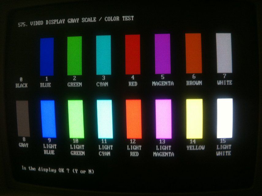
This picture shows the 16 CGA color palette in text mode - EGA uses the same 16 colors in its default palette.
Next we have a disk controller card. Modern PC's have their disk and floppy interfaces integrated onto the motherboard, but this didn't start happening until the end of the 486 era. Instead, the interfaces were installed as an expansion card.
This is an MFM hard drive controller card. MFM hard drives were the precursor to IDE. IDE stands for 'Integrated Drive Electronics', so named because the drive controller was integrated into the drive. On the older MFM drives, this controller was actually part of the interface card. There are two cables going to each hard disk drive; the wider, 34 pin cable was used for the drive controller signals. The controller basically translated requests for data from the system into instructions for the drive's head to move to the correct sector on the disk. This data was transmitted down a smaller, 20 pin cable. Also, the familiar "master/slave" jumpers from IDE drives are missing, instead each MFM drive has FOUR jumpers to choose from, usually labelled DS0-DS3 (Drive Select).
On the card you see above, there are 4 ribbon cable headers along the top of the card. The two smaller ones are for hard drive data connectors, while the two larger ones are a hard drive controller connector, and and floppy drive controller connector on the right. You can install up to 4 hard drives off the one controller connector, but each drive needs its own individual 20-pin data connector- so this card only lets you use two hard disks at once. The floppy connector on the right is the same old connector that hung around for years, and has all but disappeared from modern PC's.
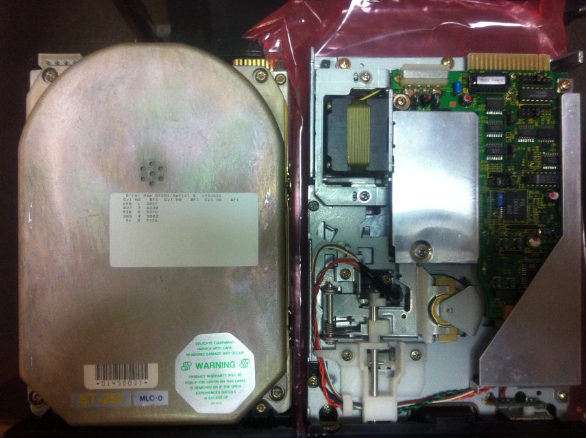
Here's the two drives that will be attached to it: on the left is the hard drive, a Seagate ST-251 42MB, and on the right is a 5 1/4" floppy drive. Notice how the hard drive is the size of a 5.25" floppy drive (same as a modern optical drive) and also has a black faceplate that sticks out the front of the case. On top of the hard drive is a white label with bad sectors noted at the factory; back then, pretty much every drive came with some bad sectors. Today, even a single bad sector on a modern drive could be grounds for a warranty return, but back then it was a fact of life.
This particular hard drive has a build date of Week 25, 1988. It would have been a fairly expensive drive when new though, as 20MB were more common at the time.
The other thing that these old drives need is a Low Level Format. Modern drives won't even let you do this, as its all configured at the factory. But on these old drives, you need to perform a low level format before the disk is usable. This basically sets up the tracks and blocks etc on the disk surface. This is different to a software format like you'd perform under DOS or Windows, which basically lays down the file system on the disk. Different disk controllers had different methods of accessing and storing this information, so you generally needed to low-level format a disk with the controller you want to use with it. With IDE drives, since the controller is integrated into the drive, low-level-formatting is all done at the factory and there is no need for an end user to perform one.
Usually low-level formatting on MFM drives was performed by a utility stored in the controller card's ROM. You had to load the dos DEBUG program, and jump to the memory address that contained the LLF utility, often C800. Unfortunately, this controller did not have such a utility built in. I ended up having to install the controller card and drive in a 386 board with an LLF utility in the BIOS, then move it back into the 286 when the format was complete.
Interestingly, the low-level-format also lets you specify the disk interleave. Basically, interleaving is placing data on disk in a non-sequential manner in order to account for processing delays and high rotational latency of older disks. Older PC's would often take so long to process data that the drive sends, that by the time the computer is ready for the next piece of data, the drive will have spun past it, and will have to spin all the way around again until the head passes over the required data. Interleaving tries to place sequential data in a fashion that accounts for these delays, so that the head will pass over the next piece of data at the right time. Of course, this means that data is not laid out on disk in a sequential manner, but that's the drive controller's problem, not the user's. This particular drive tested OK at 1:1 interleave on the 286 (so data is laid out sequentially) so thats what I went with. Using the wrong interleave can kill disk performance and can also lead to corruption problems in certain circumstances.
On to the floppy drive. Note the edge connector for the cable to attach to, rather than the pins used on modern drives. In addition, 5 1/4" drives had terminators and drive select jumpers to worry about, both of which are absent from 3 1/2" drives. Just like the MFM hard disk, the floppy drive could have a drive select jumper set to one of four positions. Also, the drive at the end of the cable needed to have a signal terminating resistor installed, or signal errors could occur. If you've ever wondered why floppy cables have a twist in them, its so that lazy system builders could just leave each floppy drive set to drive select 2. The twisted wires caused the drive at the end of the cable to be detected as drive 1. Of course, if you used a cable without a twist to install two drives, the drive at the end of the cable would need to be jumpered to drive 1.
3 1/2" drives did away with both of these - the terminators were permanently included in the drive, and it was hard coded to drive select 2. In the photo, the terminating resistor is the black object with the silver label near the edge connector.
Final step is to configure the front panel.
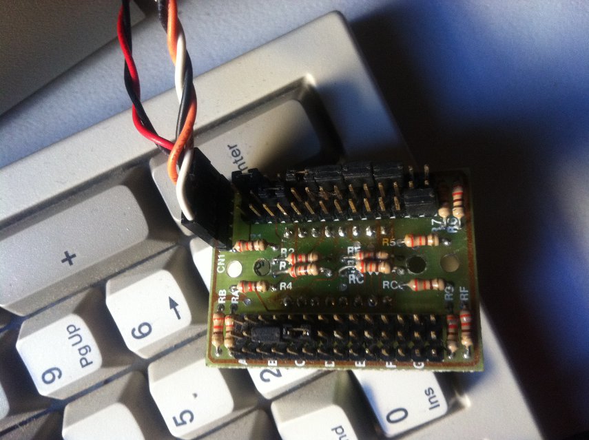
This picture shows the reverse of the digital speed display. You can set it to say whatever you like, each jumper corresponds to one segment. There are 3 rows for each 8-segment number, one row is turbo on, one is turbo off, one is common (segment is on in both modes).
I configured mine to say 10MHz in turbo mode and 8MHz when disabled.
This machine, being a turbo AT type clone, has two modes of operation - 8MHz and 10MHz. By holding Ctrl+Atl and pressing + or - you can switch between the two clock speeds. This is in addition to the turbo button on the front- the turbo button doesn't reduce the clock speeds, instead it just introduces some additional memory wait states to slow the machine down. They will work in tandem, so you can have turbo off at 8MHz for a really slow machine.
It took a bit of fiddling to discover which jumper on the motherboard performed which function. Interestingly, the turbo LED header on the motherboard isn't affected by the turbo button on the case (even though the speed definitely slows down). It instead lights up when running at 10MHz, and if you use ctrl+alt+- to switch to 8MHz it goes out. One peculiarity is that this light blinks rapidly when a floppy drive is being accessed.... no idea why.
The front panel also has a keylock - this simply disables keyboard input. The only time I've ever seen this used is at Harvey Norman on a display PC. Yet another thing missing from modern PC's (although I doubt anyone really misses it).
Anyway, with all that sorted, its time to put it together and see if it works.
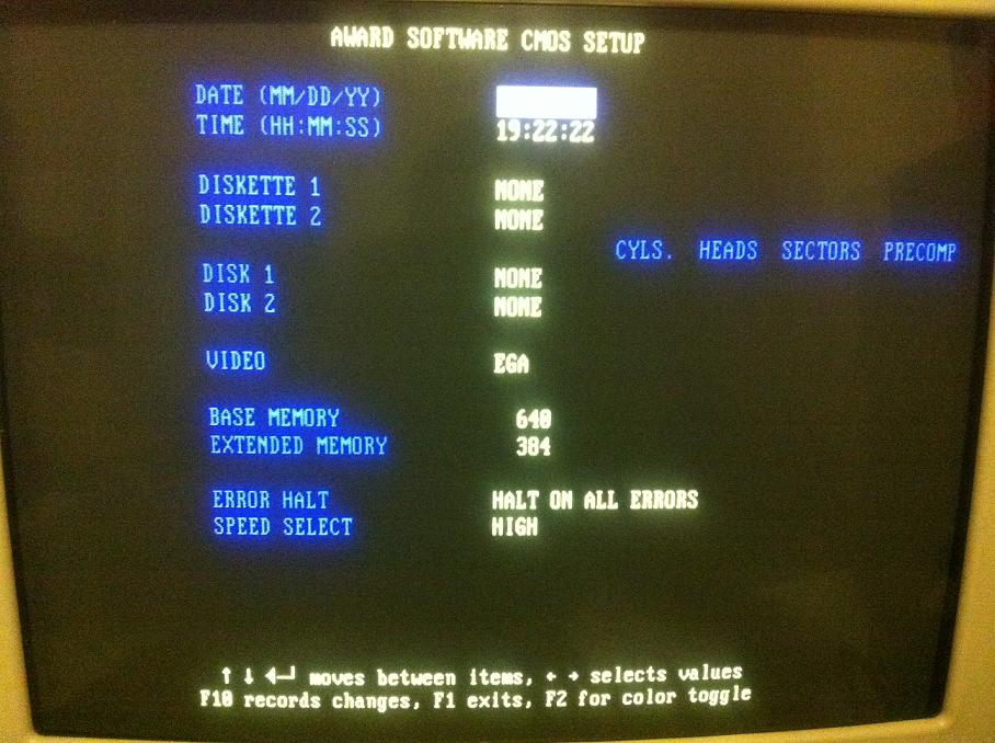
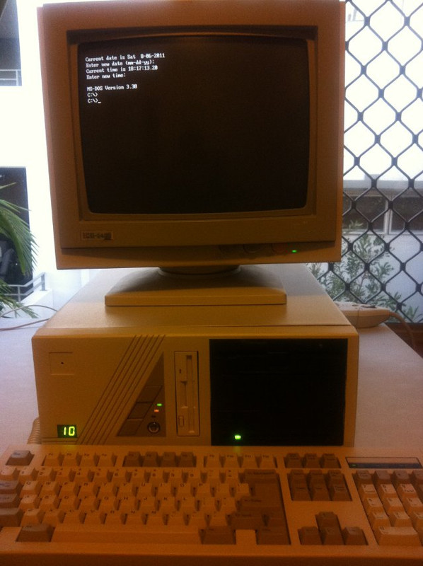
Success! here is the system BIOS setup. That's the only page. The only options in the BIOS are for date/time, disk drives, video type, installed RAM and CPU speed at bootup (for 8MHz/10MHz operation).
The BIOS also doesn't let you specify your own hard disk settings. There are about 46 disk drives to choose from, up to about 142MB. Luckily, the ST-251 is disk type 40 so this isn't a problem. Newer drives eventually came out with geometry settings that didn't conform to any of these 46 default types so you would instead enter the geometry settings in the BIOS manually. Modern BIOSes autodetect these settings for you.
Now that everything is wired up and connected, its time for the operating system to be installed.
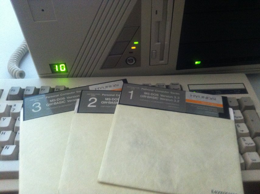
Good old DOS 😀 Here is a copy of MS-DOS 3.3 on 5.25" floppies. This version was intended for a Hyundai brand PC (they aren't just a car company you know 😉 )but its basically just standard MS-DOS 3.3, with a couple of additional Hyundai specific utilities (which we won't be using anyway).
In 1988 DOS 4 was available however it quickly gained notoriety for a number of bugs including some that caused data loss/corruption. For this reason a lot of people stuck with DOS 3.3 until DOS 5 came out a couple of years later. DOS 5 had a lot of additional features too such as a full-screen text editor (3.3 had EDLIN which only let you work on a line at a time- quite painful to use), an expanded memory manager, support for loading drivers in high memory, and so on.
The main cause of DOS 4's problems was the new FAT16 file system. The file system used on floppy disks and hard disks in early versions of DOS was FAT12, so named because it used 12-bit values to store the number of clusters on a disk. This allowed a maximum partition size of 32MB. FAT16 expanded this to what was, at the time, a mind-numbingly huge 2 gigabytes. However, full support for FAT16 wasn't introduced until DOS 4. (Compaq released their own version of DOS, 3.31, that included full FAT16 support- but the Microsoft branded DOS didn't support it until version 4).
With this in mind, I decided I didn't want to risk any problems and stick with the tried-and-true DOS 3.3. However this meant that I could not use the entire 42MB of the drive without making 2 or more partitions. I booted off the first DOS disk, and used the FDISK utility to create a 10MB Primary DOS partition (C drive) and the remaining 32MB were used as a logical drive in the extended partition (D drive). Drive C was made active, both drives were formatted.
Now that the hard disk is ready, time to run the install:
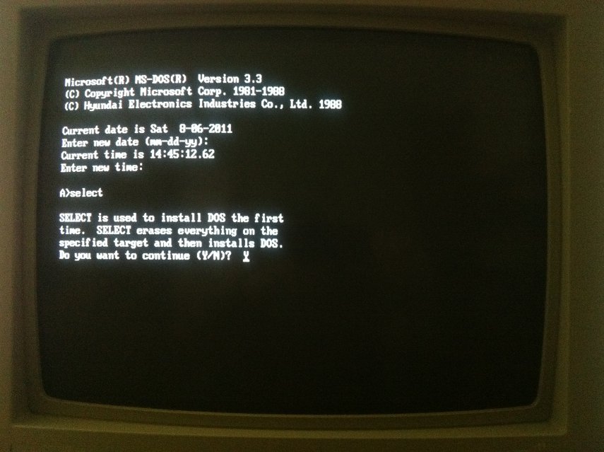
Pretty basic really, just copies the files to the C drive. Take the floppy disk out, reboot, and we have a fully functional DOS 3.3 system.
First thing I do is install Norton Utilities for DOS. These old versions of DOS don't have any way to scan the disk surface for bad sectors, and I wanted to try to avoid any problems down the line, so I use the CALIBRAT.EXE tool included with Norton Utilities to perform a scan and disk benchmark.
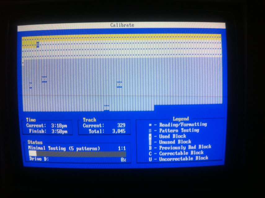
Everything checks out fine- apart from the already existing bad sectors, but that's to be expected, and they don't seem to be spreading.
So now we've got a basic 286 machine, just like one you might buy in 1988.
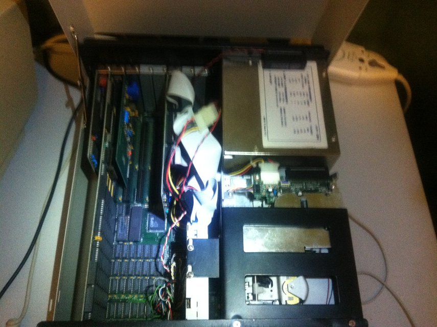
The green light on the right is the hard disk drive- it has its own power light built into it.
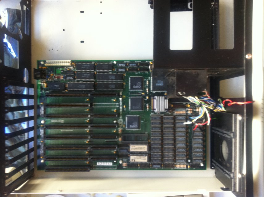
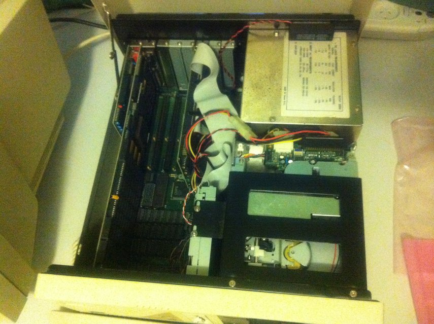
Here's how it looks inside (notice the latch on the left to hold the case open)
But where's the fun in a basic system? Let's pimp it out a bit 😀
You might notice that there is no sound card. Back then sound cards were pretty exotic- most machines did not have one. The standard sound device was the basic PC speaker which just makes primitive beeps and buzzes (although you could get rudimentary speech out of it if you were clever).
One of the first sound devices was the IBM Music Feature Card - basically a very early Yamaha MIDI synthesizer, and it was aimed at professionals with a price tag to match. Although a couple of games supported it, gaming was not its focus and its price kept it out of the hands of the average user.
Roland also released the LAPC-I - pretty much an MT32 synthesizer in an ISA card, but again, it was expensive and aimed at professionals. Sierra and Lucusarts supported it with their games but it was still pretty exotic.
There were a few other attempts at sound devices marketed at games... Tandy PC's had a 3-voice version of the PC speaker that garnered some support, and there was also the Covox Speech Thing was was a very simple circuit that plugged into your parallel port... they are actually quite easy to build yourself if you have a bit of electronics know-how. The quality wasn't earth shattering though, and of course games needed to be coded to support it.
Creative released their Creative Music System (later Game Blaster) in 1987 which used a Phillips square-wave generator chip, and sounded like a 12-voice version of the PC speaker.
The real breakthrough in PC sound, though, was when the Adlib was released, in 1987. The adlib really took off and soon became the standard for music on the PC for years to come. The Adlib used an Yamaha FM synhthesis chip, and couldn't do digital sound (like speech samples etc).
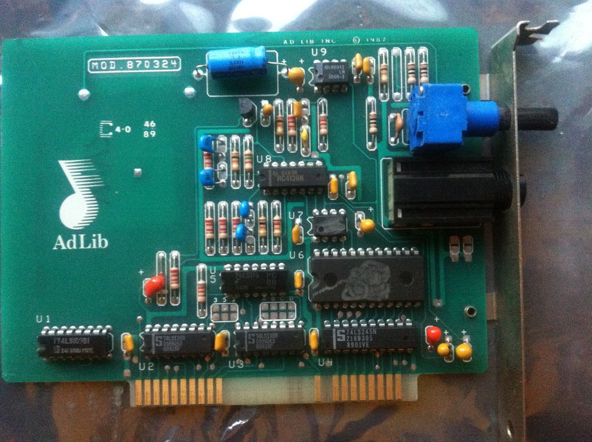
This is an original 1987 design Adlib (the design was refreshed in 1990). Notice the long volume knob protruding out the back. The speaker jack is a 1/4" TRS connector, rather than the smaller 3.5mm 'headphone' jack that later sound cards, and indeed, most devices use today.
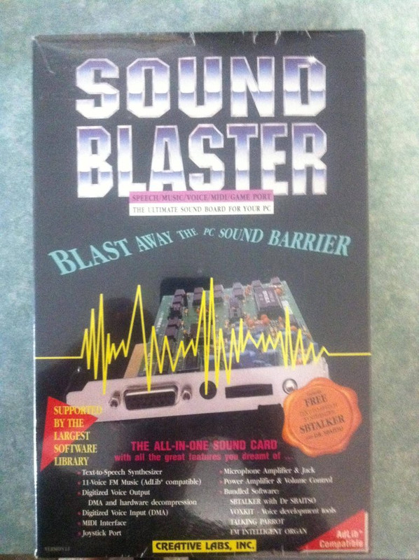
Creative would release the Sound Blaster in 1989, which included the same Yamaha FM synthesizer that the Adlib used, but added digital playback capabilities. Sound Blaster would quickly become the sound card of choice, with huge support from the gaming industry, but Adlib really kick-started the process.
Pretty much every DOS game in the early-mid 90's used FM synthesis for music, which was pioneered by the Adlib. Of course, without a Sound Blaster, you'd get no digital sound effects, only music.
The other advantage of the Adlib is that there is NO software to install, not even an environment variable to set up. The Adlib simply uses an I/O address (388h), no IRQ, DMA, or anything like that. (The sound blaster used the same I/O address to maintain compatibility). So if a game supports Adlib music it should just work.
I have both an original sound blaster and a CMS/Game Blaster in the mail, stay tuned for an update and you can check them out 😀
I do have an original sound blaster, unused in a sealed box, but I think it would be some sort of sacrilege to open it.
UPDATE: These have arrived, check out this post for the low down 😀
What about RAM? Well as you might have noticed, the motherboard's RAM slots are full up, giving us a max of 1MB. No problem- just install a RAM card in the expansion slots.
But what's the point for real mode software that can't use more than 640KB anyway? Back in the day, Expanded Memory was used to work around this limitation. Some software that worked with lots of data like Lotus 123 (early spreadsheet program) could exhaust that meager 640KB of memory easily. So the need for more memory was there - but how to get around the address limitations? Expanded Memory Specification (EMS) assigned a 64KB window of memory address space to act as a 'window'. Software could use the conventional 640kb of memory to launch themselves, then use this window to read and write data to expanded memory, which was paged in and out of the window, 64KB at a time- kind of like flipping through pages in a notepad, as opposed to the normal 1MB of memory which would be like a big poster that you can see entirely all at once.
By contrast, Extended Memory, or XMS, refers to memory beyond the first 1MB, and could be accessed by protected-mode software. XMS however was not compatible with EMS - Software had to be written to specifically use EMS. Later versions of DOS could simulate EMS in software, using XMS memory but of course this reduced the amount of XMS available for protected mode software.
Here is an Intel 'Above Board' memory expansion card, with 2MB of installed memory:
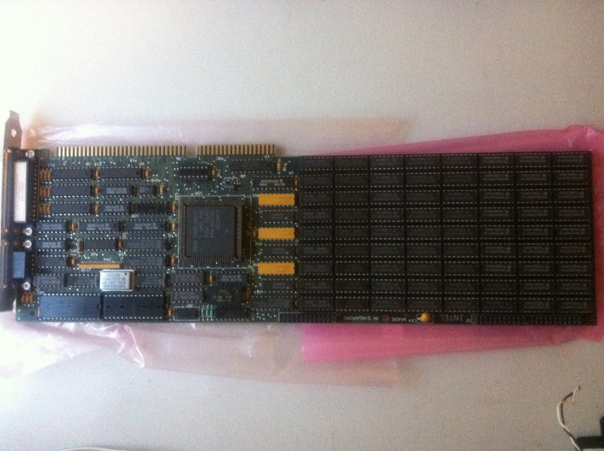
Note the size of it. It's huge! this is a full length card. You might think modern video cards are long, well, full length cards were around since the beginning of the PC, then thankfully disappeared from most consumer level PC's for most of the 90's... then made a comeback last decade 🙁
It takes up the entire length of the case:
From left to right, the installed cards are: EGA video adapter, EMS memory card, Adlib sound card, 2 free slots, Disk controller card.
Intel still has drivers for this card on their website... here's the installation utility:
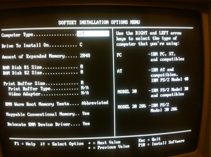
The card can be configured for both EMS or XMS memory. Since I'm not using any protected mode software, I chose EMS. If you have less than 640KB of memory on your motherboard, the card can be configured to fill up your remaining conventional memory up to 640KB too.
Its interesting that this card can be configured in software in this manner (and it keeps its settings if you swap it between PCs) - at the time most hardware was configured by jumpers. Plug and Play was still a few years away at this point.
This card also has a serial port which allows me to use a mouse - in 1988 a mouse was far from essential as Windows was still in its infancy, and most software was written with a text interface and keyboard control in mind. Mouses (mice? mousens? whatever) really gained popularity in the early 90's when Windows 3.0 and 3.1 were released.
There are no other serial ports on this machine, so this saves using a dedicated serial port card. Today such ports would be built into the motherboard- although serial ports are pretty obsolete now, most motherboards don't even bother including them - USB is now the standard for connecting peripherals.
It should be noted of course that an EMS card for a home user is an extravagance. By far the most common market for these devices was business machines running demanding software. This board would have been quite expensive to buy new.
So now that we're all set up, how are we looking?
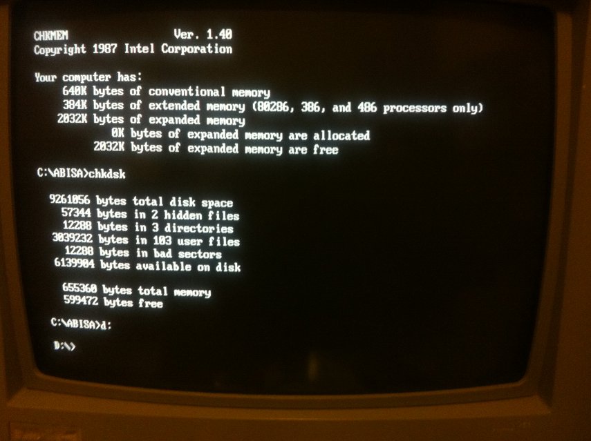
As you can see, all 2MB of the EMS card are installed and working, and with the mouse and EMS drivers loaded there is almost 600KB of conventional memory free. (DOS 3.3 lacks the MEM command so you have to use the CHKDSK command to display free memory).
So there you have it... the system is complete! A pimpin' 286 rig from the late 80s'.
Amd now the real fun begins.... GAMES!

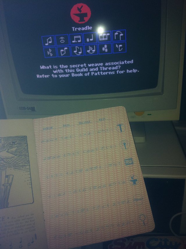
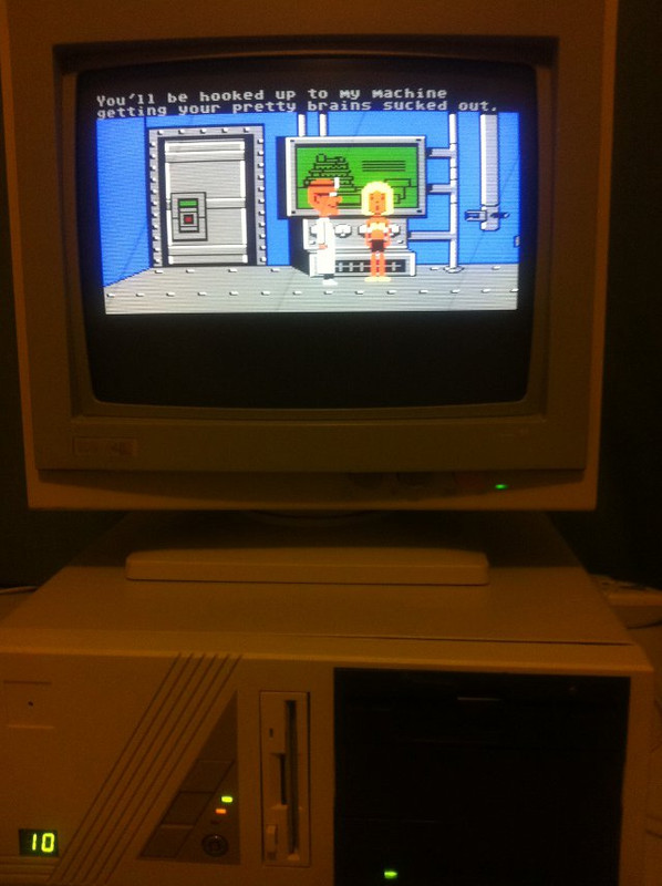
First thing I do is install LOOM and the original Sim City off their original floppies... for that authentic retro experience 😀
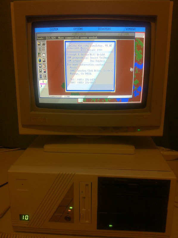
And you can't get more authentic then those annoying document checks that functioned as early copy protection:
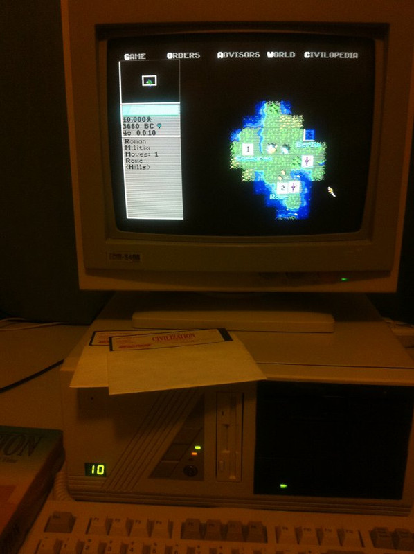
We can't forget that timeless classic, Civilization
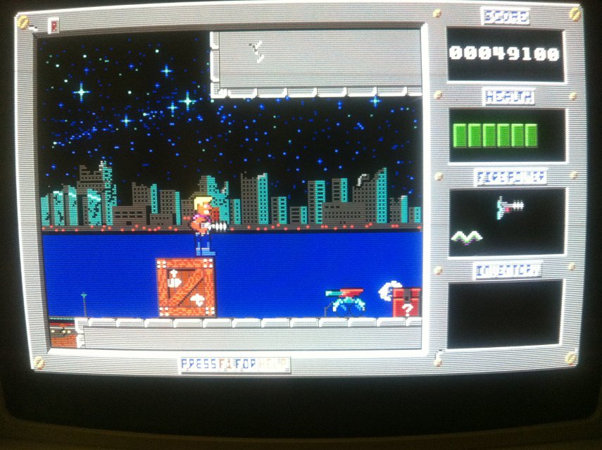
Duke Nukem has been in the news recently with Duke Nukem Forever finally being released, so its seems appropriate for a quick flashback to where it all began
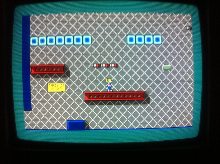
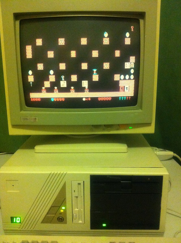
And of course, THE 286 game, Commander Keen
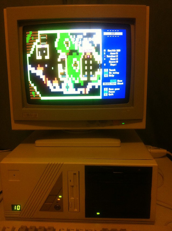
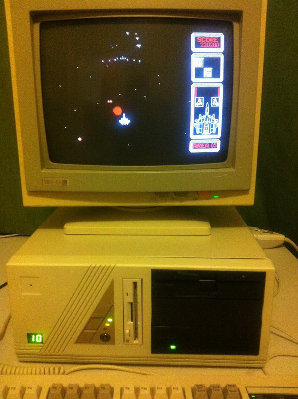
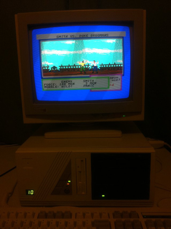
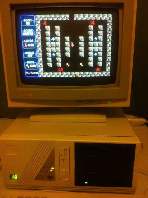
Some other games I've been hitting are ZZT, Silpheed, Sid Meier's Pirates!, Maniac Mansion, Pharoah's Tomb, Railroad Tycoon and Paganitzu.
So there you have it! My 286 is finally up and running after taking way too long. I must say there is really something special about playing these old games on the hardware of the era 😀 Hope you enjoyed reading this as much as I enjoyed building and playing on it!


