VOGONS


Reply 20 of 42, by Oldskoolmaniac

User metadata
Rank Oldbie
Rank
Oldbie

mine has the solder holes and if -ve dosnt lead to any thing ill leave a discrete wire running on the back of the board. Ill post pics and explain my work.

Motherboard Reviews The Motherboard Thread
Plastic parts looking nasty and yellow try this Deyellowing Plastic

Reply 21 of 42, by Errius

User metadata
Rank l33t
Rank
l33t

Attached pics of battery area from a version 1.2 board:

Attachments

  • 1.2 battery under.jpg
    Filename
    1.2 battery under.jpg
    File size
    50.07 KiB
    Views
    1103 views
    File license
    Fair use/fair dealing exception
  • 1.2 battery top.jpg
    Filename
    1.2 battery top.jpg
    File size
    175.08 KiB
    Views
    1103 views
    File license
    Fair use/fair dealing exception

Is this too much voodoo?

Reply 22 of 42, by Robert B

User metadata
Rank Oldbie
Rank
Oldbie

This is very important to me also, as my Acorp 5VX32 motherboard has and ODIN battery and solder holes for the coin battery socket. I would like to remove the ODIN and solder a coin battery socket for convenience.

Attachments

  • battery2.jpg
    Filename
    battery2.jpg
    File size
    23.8 KiB
    Views
    1079 views
    File license
    Fair use/fair dealing exception
  • battery.jpg
    Filename
    battery.jpg
    File size
    56.55 KiB
    Views
    1079 views
    File license
    Fair use/fair dealing exception

Reply 23 of 42, by Oldskoolmaniac

User metadata
Rank Oldbie
Rank
Oldbie

You will still have to keep the odin as traces run to it.

I just got the coin battery holder today, ill try to get around to soldering it in.

Motherboard Reviews The Motherboard Thread
Plastic parts looking nasty and yellow try this Deyellowing Plastic

Reply 25 of 42, by Oldskoolmaniac

User metadata
Rank Oldbie
Rank
Oldbie

Not successful
But here is where I am so far:

1315669616.or.50593.jpg

Attachments

  • IMG_1487.JPG
    Filename
    IMG_1487.JPG
    File size
    1.81 MiB
    Views
    1062 views
    File comment
    Even tried running that wire to the odin
    File license
    Fair use/fair dealing exception
  • IMG_1483.JPG
    Filename
    IMG_1483.JPG
    File size
    1.21 MiB
    Views
    1062 views
    File license
    Fair use/fair dealing exception
  • IMG_1482.JPG
    Filename
    IMG_1482.JPG
    File size
    1.71 MiB
    Views
    1062 views
    File comment
    Had to shave the holder a little to fit next to that jumper
    File license
    Fair use/fair dealing exception

Motherboard Reviews The Motherboard Thread
Plastic parts looking nasty and yellow try this Deyellowing Plastic

Reply 26 of 42, by Oldskoolmaniac

User metadata
Rank Oldbie
Rank
Oldbie

pin 22 is also NC, should I hook the positive into that one?

Motherboard Reviews The Motherboard Thread
Plastic parts looking nasty and yellow try this Deyellowing Plastic

Reply 27 of 42, by Errius

User metadata
Rank l33t
Rank
l33t

Hmm, I think we are in trouble. This picture shows that this chip doesn't have pins 16 and 20. looks like cutting into the insulation is the only way to do this.

It's missing pins 2 3 16 20 22

Attachments

  • oec12c887a-odin[1].jpg
    Filename
    oec12c887a-odin[1].jpg
    File size
    15.59 KiB
    Views
    1057 views
    File license
    Fair use/fair dealing exception

Is this too much voodoo?

Reply 28 of 42, by Oldskoolmaniac

User metadata
Rank Oldbie
Rank
Oldbie

so will have to remove it?

Motherboard Reviews The Motherboard Thread
Plastic parts looking nasty and yellow try this Deyellowing Plastic

Reply 29 of 42, by Errius

User metadata
Rank l33t
Rank
l33t

I think so, unless you can file away the insulation with the chip in situ. That sucks. I was hoping there was a simple solution to this problem.

Is this too much voodoo?

Reply 30 of 42, by Oldskoolmaniac

User metadata
Rank Oldbie
Rank
Oldbie

ok I got it figured out after hacking away at the odin those two missing pins are folded over bend them down so they are touching the solder spots and you still have to run the one trace. Ill have to clean mine up better, cause it looks like a hack job, but at least my time is staying current now.

Motherboard Reviews The Motherboard Thread
Plastic parts looking nasty and yellow try this Deyellowing Plastic

Reply 32 of 42, by Oldskoolmaniac

User metadata
Rank Oldbie
Rank
Oldbie

I also found this: http://stason.org/TULARC/pc/motherboards/M/MI … um-MS-5129.html is it true that this board can run a k6 at 90fsb

Motherboard Reviews The Motherboard Thread
Plastic parts looking nasty and yellow try this Deyellowing Plastic

Reply 33 of 42, by Oldskoolmaniac

User metadata
Rank Oldbie
Rank
Oldbie

Bring those two pins down and solder the one wire on the back to unable the negative trace and you will be able to use the holder solder points

Attachments

  • IMG_1489.JPG
    Filename
    IMG_1489.JPG
    File size
    1.33 MiB
    Views
    1031 views
    File license
    Fair use/fair dealing exception

Motherboard Reviews The Motherboard Thread
Plastic parts looking nasty and yellow try this Deyellowing Plastic

Reply 34 of 42, by Robert B

User metadata
Rank Oldbie
Rank
Oldbie

A+++ for your efforts - it is a valuable information.

Keep us updated on how it performs. If the BIOS settings are kept or any other anomaly.

I think I will remove the ODIN entirely so that I can work in peace and put a pin socket for it. I think it is best this way.

Or I'll buy a few ODIN replacements. Unfortunately in my country they arent easily available.

Reply 35 of 42, by Errius

User metadata
Rank l33t
Rank
l33t

Yes very cool. Since the board has a place for a 3V battery it seems appropriate to use it. I'm wondering if the wire connection to pin 16 is necessary.

Is this too much voodoo?

Reply 36 of 42, by Oldskoolmaniac

User metadata
Rank Oldbie
Rank
Oldbie

^Yes pin 16 is necessary

You have to leave part of the odin, there is chip under all that plastic, also when you start drilling through the odin's plastic you will run into a tiny battery, pull that off. you just have to expose those two pins from the side and bend them down so they make contact with the solder holes.

I wish had a dremel to do this as I was using a dull knife and a drill, carefull how far you go cause you will hit a ceramic chip.

By the way what is the limit to these boaed like what Dimm RAM stick can I use, whats cpu and how big of a HDD?

Could anyone link me to the latest bios?

Motherboard Reviews The Motherboard Thread
Plastic parts looking nasty and yellow try this Deyellowing Plastic

Reply 37 of 42, by Tetrium

User metadata
Rank l33t++
Rank
l33t++
Oldskoolmaniac wrote:

By the way what is the limit to these boaed like what Dimm RAM stick can I use, whats cpu and how big of a HDD?

Could anyone link me to the latest bios?

HDD depends on the BIOS mostly.

430VX does support SDRAM, but only the earliest ones that were basically either 16MB (8 chips on 1 side) or 32MB (16 chips on both sides).

Many boards of that time had warnings to not use SIMM and DIMM at the same time, iirc due to different voltages.
Newer SDRAMs might work, but you'll probably run into the problem that only part of the memory is recognized (like for instance putting in a 64MB stick and only seeing 16MB). I don't know if there may be any problems with using more recent SDRAM (like PC-100 or more recent), SDRAM was still in its infancy.

430VX boards with 2 DIMM slots are nice as that way you could use SDRAM and go up to the maximum cacheable area of 64MB.

430HX sometimes also comes with DIMM slots but the chipset doesn't support SDRAM.

CPU depends mostly on BIOS support (check that Jan Steunebrink page) and the availability of lower voltages. It really depends on the board itself.
Many boards of the time used linear VRMs that generated more heat the lower the CPU voltage went.
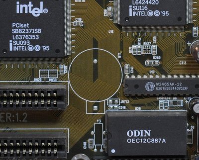
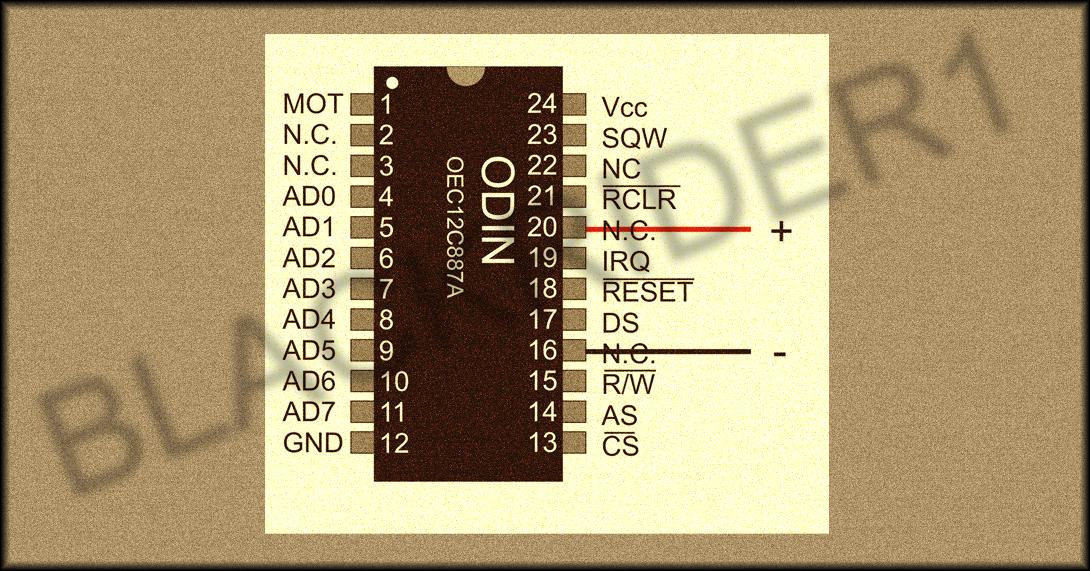
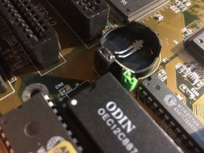
Whats missing in your collections?
My retro rigs (old topic)
Interesting Vogons threads (links to Vogonswiki)
Report spammers here!