Reply 780 of 844, by Robert B
- Rank
- Oldbie
CPU Socket "replacement" without special tools aka MSI K7D Master-L MS-6501
Before we get to the matter at hand, we must first read the following lines:
Socket A mechanical load limits
AMD recommends that the mass of a Socket A CPU cooler to not exceed 300 grams (10.6 ounces). Heavier coolers may result in damage to the die when the system is not properly handled.
All socket A processors (Athlon, Sempron, Duron and Geode NX) have the following mechanical maximum load limits which should not be exceeded during heatsink assembly, shipping conditions, or standard use. Load above those limits may crack the processor die and make it unusable.
Location Dynamic Static
Die Surface 445 N(100 lbf) 133 N(30 lbf)
Die Edge 44 N(10 lbf) 44 N(10 lbf)
What does the text above tells us? Well, for what I am going to present today, the most important aspect is the one related to the 300g weight limit regarding the socket A CPU coolers. This is not about chipped CPU dies or coolers installed incorrectly. I never had this problem and I did my share of stupid things.
Ever since I read about that 300g weight limit, the first question that popped in my mind was: WHY? You see, back in the day I never had problems related with the weight of the CPU coolers, but also, I never had to mount a heavy CPU cooler on my CPUs.
So what's the stuff with the weight restriction regarding the socket A CPU coolers?
As the story will unfold you will get an insight that now is a well known fact to me. Back in the day this might've never been an issue but as it happens, many times we take for granted things that aren't meant to be taken for granted.
So without any further ado, let's get on with the show! 😀
It all started, on a wet, cold, rainy day at the local flea market. There wasn't much to be seen and I wasn't holding much hope that things would change on that faithful day.
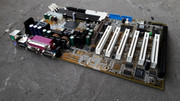
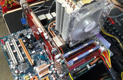
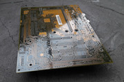
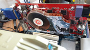
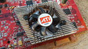
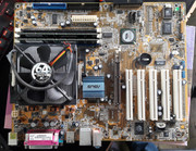
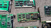
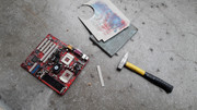
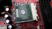
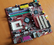
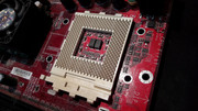
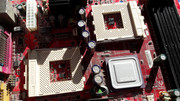
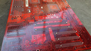
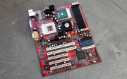
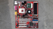
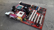
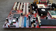
Like many times in the past, I was proven wrong and fate made that I found this huge red beauty lying on a wet and dirty bed sheet, begging to be saved.
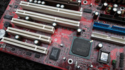
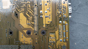
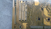
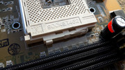
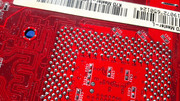
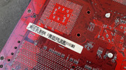
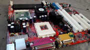
I looked at it and I quickly assessed the situation. What was to be assessed? One look and all you could see was that the board was disfigured. A once mighty piece of tech now a decayed and deprecated mess. The second CPU socket also had a partially torn middle hook but the rest were okay.
I really hate when this happens. I might be too sensible or too involved as I felt the pain of this red mother of all boards. DAMN IT!
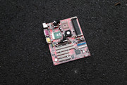
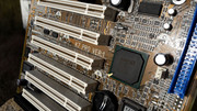
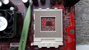
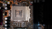
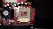
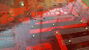
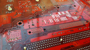
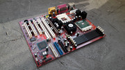
Should I zoom in?!
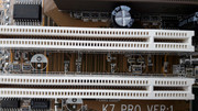
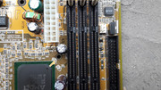
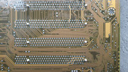
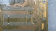
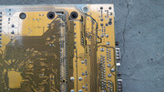
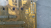
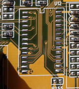
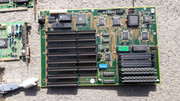
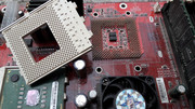
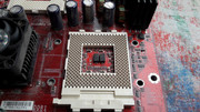
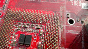
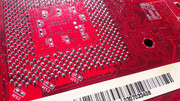
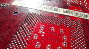
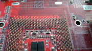
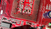
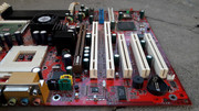
Yep. There seems to be a slight problem with this motherboard. IT IS MISSING AN ENTIRE CPU SOCKET!!!
Other than the minor fact pointed above there was little wrong with the MSI K7D Master-L. This was a fresh kill as I could still pick up the scent of the perpetrator. A recycler-predator or a Cro-Magnon human had its way with this RED HOT board. Damn! If only the dice would've rolled a higher chance for a saving throw! $#&*$*(#&*($(#*&##!!!!

I bought the board without blinking an eye. You see, with experience comes confidence and with confidence you can achieve almost anything. If you believe in something then there is nothing to stop you from trying something.
For many years I roamed the flea market and I have seen my share of socket A motherboards missing their heart and soul, namely the all important CPU socket. Without it there is no coming back from the brink. Many times I thought that those boards were a write off as the damage seemed to be terminal or close to that. Now I have a solution even for this. The mind is a beautiful thing!
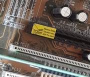
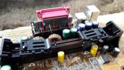
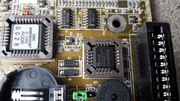
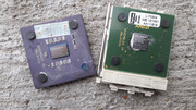
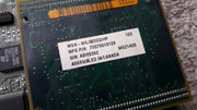
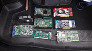
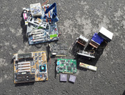
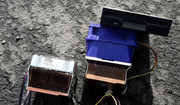
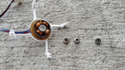
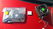
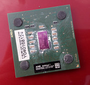
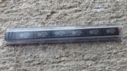
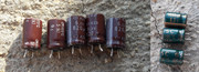
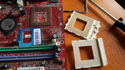
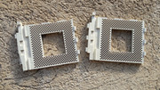
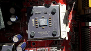
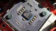
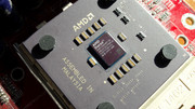
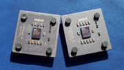
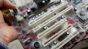
The thought that gave birth to the idea that I put in practice in this episode, came to fruition after I found these CPUs, many moons ago. The fact that they came with the plastic shell of the CPU socket was out of the ordinary.
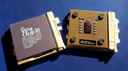
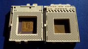
The pictures above tell something that it is blatantly obvious. It is very easy to remove the plastic shell from a socket A CPU socket and also from a socket 7 CPU socket. Ever since I saw this, I saved a sector in my mind and I stored that information for future use. The mind has a curious way of putting things together.
Now comes into play the weight limit restriction for CPU coolers that I mentioned at the start of this thread. You see, as the CPUs got faster so the cooling requirements got tighter. Bigger more performant coolers were required to cool the beasts running faster and faster. This wasn't an issue at first but it got pretty serious later and it goes on to this day. Better coolers had a bolt through mounting mechanism but at the age of the socket A stuff, this was, should we say exotic? Even if motherboards had mounting holes for coolers, I never saw one in the flesh or remember reading about one that made use of those holes. Even if I knew about them, pfft, who needs that stuff when we have clip on CPU coolers that do the same job?!?! This doesn't mean that they didn't exist, it is simply that I considered this information as unimportant. This also means that I have some catching up on that info. Good Ol' Internets to the rescue.
But I digress ...
As I really wanted to save this motherboard, my mind searched relentlessly for a solution. One was a complete CPU socket replacement which was a daunting task for someone who lacks the required tools. Even with the best tools there is no guarantee that things will go according to plan. To this day I still rely on ancient soldering irons, 15W, 40W, 80W, with unregulated temperature and a 100W soldering gun. 😁 I might have a couple of screws loose but I tight them up on a regular basis! 😁
There has to be an easier solution! All the pieces of the puzzle were in the correct place. Then it hit me!
Guinea pig? CHECK! Replacement CPU socket? CHECK! Able and willing? CCCCCCCHHHHHHHHHHEEEEEEEEEEECCCCCCCCCCCCCKKKKKKKKKKKKKKKK!!!
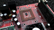
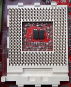
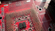
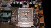
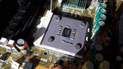
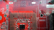
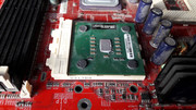
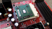
By sheer luck, all of the pins from the CPU socket were in a perfect position. What were the odds?!?!? So what are you waiting for?!?!?
Slap that plastic shell on that puppy and POWER IT UP!!!
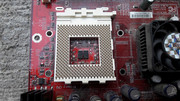

The matter of putting back the plastic shell on a socket A CPU socket is as fiddly as a mistress but it is also very easy to be done.
You have to:
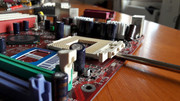
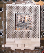
1. Start from one side, preferably from the side with which forms the back side of the CPU pins. The part that normally has the Socket 462 string written on it. Starting from the front of the CPU pins means dealing with the tiny hooks of the pins and that is asking for trouble.
2. Work your way through, slowly and gently. Feel each pin through the tips of your fingers.
3. Check to see that row after row of pins, get into their corresponding hole.
4. Row after row, at some point, you will feel that the plastic shell slides in by itself.
5. You are home free.
Easy as that. I am not kidding.
Who knew that CPU socket "replacement" was so easy! You even don't need special tools! It doesn't come easier than that folks!!!
Little did I know, that on my first try, as it is ALWAYS the case, you make all the mistakes and then some! Phewwww!!! I was in for a ride and it was awesome!
I always thought that CPU sockets were as sturdy as they come. That nothing could move them. They are there to stay.
WRONG!
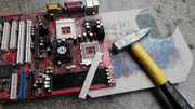
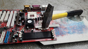
At the moment in time when I was performing the surgery described above, I was thinking that the plastic shell from the CPU socket had to have some kind of retention mechanism so I took things further and I used a .... HAMMER! Yep! I still laugh when I remember that moment.
Don't worry, the hammer wasn't used to hammer stuff down, it was just used to gently tap on the plastic shell while I used thick pieces of cardboard as cushion on the plastic shell and under the motherboard. I may be mad but not that MAD!
I must confess that while I "hammered" away, I heard an echo in my mind: "All parts should go together without forcing. Therefore, if you can't get them back together again, there must be a reason. By all means, do not use a hammer. IBM maintenance manual 1975".
What was that? Must've been the WIND! 😁

To be sure that things are how they are supposed to be, I also used a pair of fine tweezers to gently bend the pins into a position that I thought was correct. This step wasn't necessary but I found out this only later. When you go into uncharted territory there is bound that STUFF will happen! DUDE!

I was ecstatic. Dunk with success. A feeling that cannot be put into words.
When I got home I checked the pictures to see what I have accomplished. I even opened a cold refreshing one to celebrate.
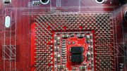
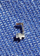
My victory was short lived though, as upon a close inspection of the pictures I got some bad news. My flawless victory wasn't so flawless after all ...
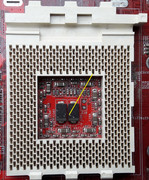
YEP! A God Damned &*#&*(#%(&#(&)(*!!!!!!! bent PIN!!!! F....................................K!!!!!!!!!!!!!!!!!!!!!!!!!!!!!
I took all of the precautions. I checked and double checked. I even triple checked but I still screwed up. BIG TIME!
I took a deep breath and I evaluated my options. There weren't too many. Without finishing my beer I went to where I keep my stuff, (the other part of the town) and I checked to see if what I saw in the pictures was true. And boy was it TRUE.
^$#^&*^$#^$&#^&*$^#&*@#$(*!!!!!!! NOOOOOOOOOOOOOOOOOOOOOOOO!!!!!
To really understand what I felt is hard to put into words. To some, what I do might seem trivial but to me it is a matter of life and death. When I do some damage, even unintentional, it is something that I feel organically. Don't worry though as I recover quickly. 😀 I have a thick skin and each such experience is treated as a learning experience. Ever since I know myself I have always been a perfectionist but only when it come to me or to what I do as I take people as they are. I learned way back that people do not change or change very little. We should take everyone as they are. But I digress again ...
So, I Fed UP BIG TIME! Bent pin and all ...
I took the rest of the day off.
The next day, a Sunday I was back at the flea market. This time I bought a donor board to see if that 300g weight limit was true. You see, there was something fishy about that plastic shell and I just couldn't put my finger on it. This required more investigation.
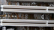
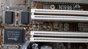
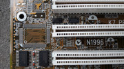
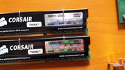
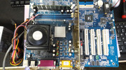
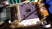
Enter an MS-6777 K7N2GM-L. Ignore all of the extra plastic connectors for CD-IN and such, as I took the liberty to "steal" many of them from other damaged boards to be used to complete other boards in my collection. This was just a means to transport them. 😁 The MS-6777 was trashed and one corner was almost missing. Poor thing. Nevertheless you will get to live in many other motherboards so I thank You for that! I said to it.
Go figure. A RED HOT mobo rescuing another RED HOT mobo. How quaint ...
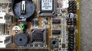
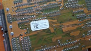
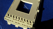
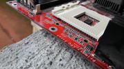
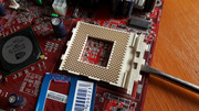
There I was with a socket A CPU socket in front of me. The top plastic cover and steel lever removed. The pins inside were a carbon copy of the ones on the MS-6501.

Let's test the 300g limit!
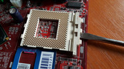
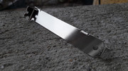
Shock and awe! Too easy to remove for comfort!
Using a flat head screwdriver with the required width plus some pieces of an old credit card as cushion, I removed the plastic shell in a matter of seconds. WOW! This is too easy! And to think that to that date I handled so many socket A boards by holding the CPU cooler. This was equal to asking for trouble. Damn. Once you overcome the initial threshold required to remove the shell and lift it a little, you just have to use your fingers and it comes off! What the actual ...
Sure, when the CPU is in, friction is multiplied by all of the tiny CPU socket pins, clinging to the CPU pins, but still, this was a shock. Removing the plastic shell without the CPU mounted is easier as the cooler weight limit refers to a mounted cooler but I wasnt prepared for this.
After all the "hammering" I thought that the plastic shell was sitting tight on the K7D Master-L.
WRONG! It came out easier than it went in! What the F......K ?!?!?!!?!?
Now was the time to inspect the damage that I inflicted on my precious MSI K7D Master-L.
Things were looking grim.
One pin collapsed on itself and it broke off when I tried to straighten it up. HOW COULD I not feel it?! If I had a hammer ... all day ...
&*#&$#$%^#&*$%*@^#)!%#$^!(#&!%^%!!!!!!

So there I was with a board that looked worse than it came in, wondering where it all went so wrong. The road to HELL is paved with GOOD intentions!!!
I took a deep breath and I shook off all of the negative thoughts.
Square ONE. Let's start again. This time FTW!!!
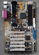
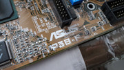
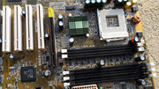
I had another socket A motherboard that had a damaged plastic shell on the CPU socket. An ASUS A7A266. Some may say that it is an unremarkable board but as it is the only socket A motherboard with an ALi chipset that I own, it is quite special to me. Not to mention that it is looking quite snazzy. After all it is an Asus (pronounced correctly like on the YT clips) board. It doesn't come more A S U S than that folks!!! 😁
So what did I stand to lose? A damaged ASUS board and a donor MSI MS-6777 board? Pfftt, I LIKE THE ODDS!!!
LET'S DO IT!
I performed on the A7A266 the same surgery I did on the MS-6501.
Needless to say that it was a complete SUCCESS!!!
There is still HOPE for the MS-6501!
With renewed forces I was ready to solve the issues of the dual headed monster! FTW!!! FTW!!! FTW!!!
Let's END THIS!!!
The first thing that popped in my mind was to desolder the damaged pin. I took the MS-6777 and with the help of the 15W (unregulated) soldering iron I removed 4 pins quite easily.
Oh YEAH!!! I GOT THIS!!!
Hold your horses! When it came the time for the real deal, removing the VCC_CORE M8 pin from the MS-6501, I hit a brick wall. I tried many things, even a 40W soldering iron, I tried to heat the board with a hair dryer, all the tricks I could think of given the tools at my disposal.
Nothing worked. *#(&%&#^(&^$#_%@&*^!!~~~~~~!!!!!!
After several futile attempts I took a moment to assess the situation. In case you are wondering nothing got damaged. I must say that I did things that I won't speak of, while I tried to remove the damaged pin. All for nothing. If there was a moment that told me that I need better tools it was that moment. Needless to say that I took note but I didn't give up. I needed to sort this motherboard not later but NOW! I was relentless.
When I saw that I wasn't able to safely remove the pin from the MS-6501 even if I was able to safely remove the same pin from the MS-6777, I came up with a bodge, ahem alternative solution.
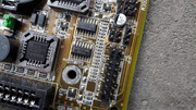
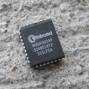
I removed the top part from one pin from the MS-6777 and I soldered it on the MS-6501.
The whole deal was quite tricky. Aligning and soldering the pin required all the hands of the Shiva Goddess but I managed to do it with just two. All in all, it took about four tries to get it right. After soldering the missing part of the pin I ended up with a THICC pin so I had to enlarge the hole in the plastic shell to accommodate the THICC shortstack (gf) pin. Well, take the good with the bad. This isn't pretty but it works. I might desolder the pin when I get the required tools but if it works why mess with it?!

Putting back the plastic shell was a trivial task. Muscle memory and experience were there to guide me. Slowly, gently, this is how a socket is made whole again. RISE my precious. RISE AND SHINE!!! (nondescript incantations in the background).


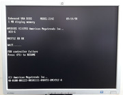
Did it fly? Ahem, work?!
Well, ...

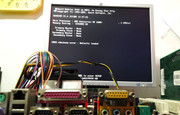
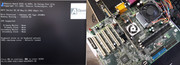
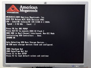
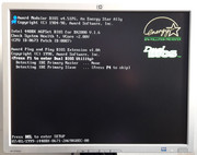
After I powered up the board, even if I knew that there was no reason that this wouldn't work, albeit the board being literally dead, I was filled with an energy that it is hard to describe. Mental orgasm might cover half of it. I felt that I could do anything, even bend space and time continuum ... ( just kidding).
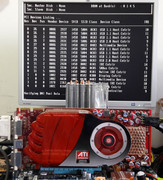
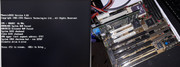
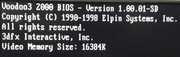
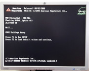
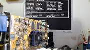
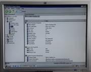
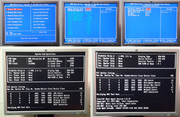
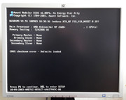
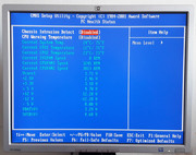
After the good news, I started experimenting with various BIOS versions to see what makes this board tick. https://www.voodooalert.de/board/forum/index. … for-bios-files/
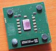
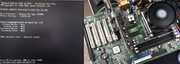
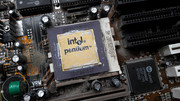
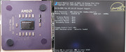
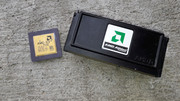
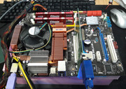
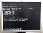
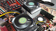
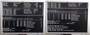
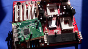
As I only had an AMD Athlon MP 2600+ AMSN2600DKT3C that came with the board and I wanted to test the dual CPU function, I looked for alternatives. On the internet I found that some Duron CPUs with Morgan cores are MP capable so I decided to try it out. I went for broke and I mounted a pair of AMD Duron 1.3GHz with Morgan cores. This didn't go according to plan but at least the two CPUs have been recognized sign that the board was @100%! NICE! I must confess that a few years back I could've bought 10 AMSN2600DKT3C for a trivial sum but I didn't. I mean who needs Athlon MP CPUs? Right?
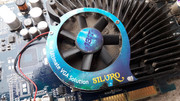
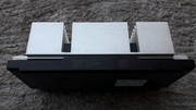
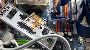
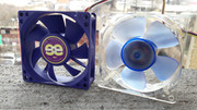
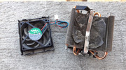
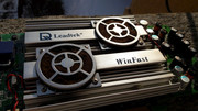
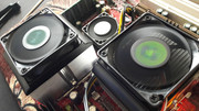
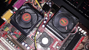
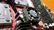
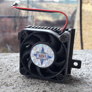
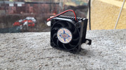
The stock AMD Socket A CPU coolers from the previous episode have been put to good use. I LIKE THEM!!!

So there you have it. CPU socket "replacement" for the dummies. All you need is basic tools and common sense. Lack of any of those means that you should not attempt to perform the operation described above.
I did all the mistakes and then some, so that you won't have to do them. So please take notes.
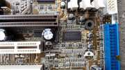
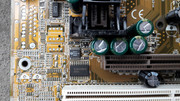
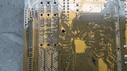
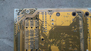
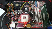
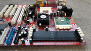
After the "mechanical" part has been solved I had to do what I do best. Restoring this mother (f) of all boards. Yeah! Get restored ... (non descript words included) !
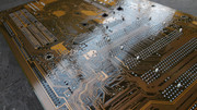
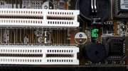
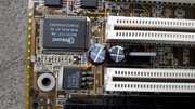
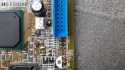
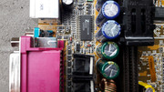
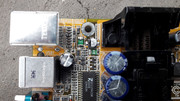
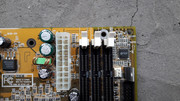
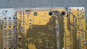
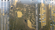
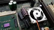
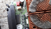
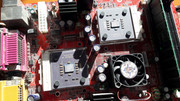
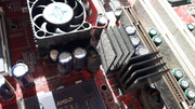
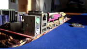
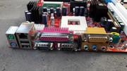
The board was dirty with thick deposits and mud on some parts, like the PS/2 connectors and the cooler on the NB.
DURON POWA!!!
Don't worry. Where does it hurt? Let me take care of that!

Vintage TIM! YUMMY!
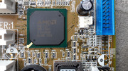
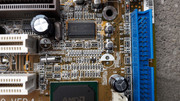
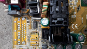
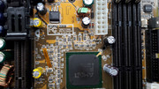
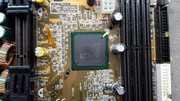
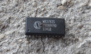
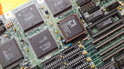
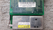
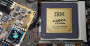
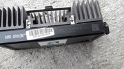
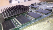
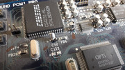
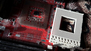
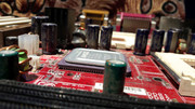
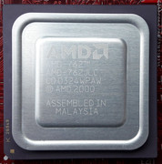
The mighty AMD-762.
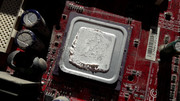

The package of the AMD-762 reminded me of the CPU package of the Slot A CPUs. Interesting.

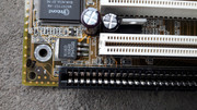
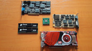
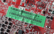
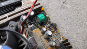
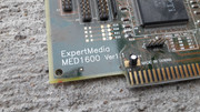
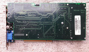
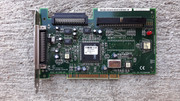
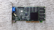
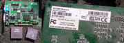
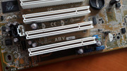
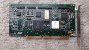
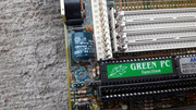
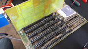
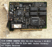
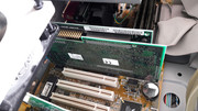
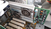
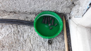
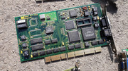
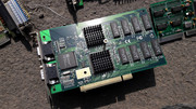
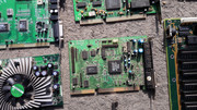
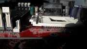
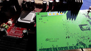
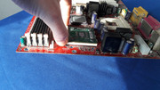
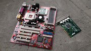
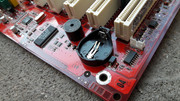
I forgot to mention that the board came with the optional MS-9516 VER:100 4-port PCI Adapter Card. This was included in the package with the MS-6501 because at launch there was a problem with the onboard USB ports so this was a solution to this shortcoming. Neat! Funny fact. On Saturday I didn't buy the MS-9516 but after I read on internet that is came with the MS-6501, the next day, on Sunday I went back and bought it. Lucky me that the seller was still there. 😁
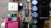
The MS-9516 cleaned up nicely. I mean look at it! It is green and shiny!
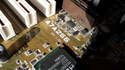
Things were looking up and I had little reasons to worry. Little did I know. When I thought that I was out of the woods, I was faced with the following issue.
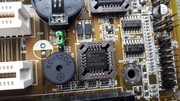
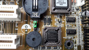
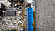
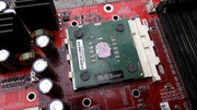
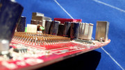
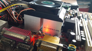
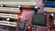
While the CPU was in the socket and the cooler mounted I didn't notice that the plastic shell of the socket would lift from the board. It flexed a little while the cooler was clamped but it was tight and I could handle the board just by holding the cooler. (Don't do this though, 300g and all ...).
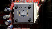
So I was faced with this.
I was shocked at how easy was to remove the plastic shell from the CPU socket. What the ... 101 dalmatians is this now?!?! I mean I just lift it with my fingers and it moves?!?!

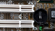
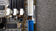
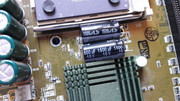
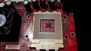
With this happening I got a definitive answer, to the normal question: How is the plastic shell fixed onto the pins when there are no physical means that keep it in place? Before this development no matter how hard I searched for an answer I couldn't came up with a conclusive one. I had a hunch but it was, you know, just a hunch.
Now the answer was staring me in the eyes.
Yep. Good Ol' friction as I said earlier. Nothing more. 300g. Shuffle the info and spit out the answer. All those many tiny pins are held into tiny slim grooves in the plastic shell. Nothing more. I was shocked to say the least. I was expecting more. Like lets say a few pins with odd shapes that would hold tight on the plastic shell but there were no such exotic measures in place. Man ... 300g ... Now I understand, even if in practice I still feel that the socket is stronger than that. Well, we'd better use those mounting holes around the CPU socket when we need beefy coolers or we move our vintage systems around, or else.
Sure, maybe the fact that the MS-6501 CPU socket has been handled with brute force might explain why the plastic shell came out so easy but is this all that there is to it? It seems so.
I even went so far to try another plastic shell. Nothing changed. For sure, something happened with the shape of the pins or maybe the plastic shell being a recovered one had its grooves enlarged in the process ... the plot thickens ... this is madness ...
I checked the ASUS A7A266 and to my relief the plastic shell held on tightly as it should. So what gives?
When I tweaked the pins on the MS-6501 I meant that I put them in a position that I thought was correct and I didn't use too much force. They weren't deformed or bent as they were already in their tiny holes and there was no room to manoeuvre.
Well, I think that there is a huge difference in the way the plastic shell is removed. Forcefully or purposely.
So what did I do with the MS-6501? Nothing. I just mounted a CPU that will be there at all times. Friction to the rescue. I was able to hold the whole motherboard by the replaced socket and it didn't move at all.
This was a roller coaster ride of the most extreme type. In the end I got more than I hoped for. I was thankful for this. I still wanted more but there was nothing more to be gained from this so I stopped thinking about it.
This board is awesome. A true survivor. Nothing more to be said.
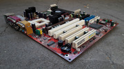
The restoration procedure carried on without a hitch.
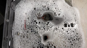
As the board already had an encounter with water I did the right thing and I added MORE water and some dish soap for good measure. Did I mention that the water was HOT? NO? My bad! 😁
Uhhh! Look! A RAINBOW!!! (not a real one of course, any resemblance with the real thing is purely coincidental unless stated otherwise...)

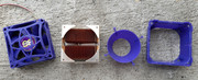
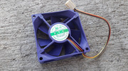
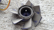
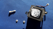
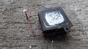
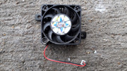
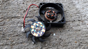
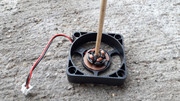
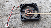
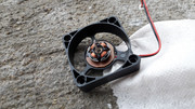
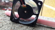
The NB cooler has been washed entirely with hot water and dish soap. Fan and heatsink. As the fan had a tendency to become stuck even after I cleaned it and lubed it, I polished the sleeve bearing with a bamboo stick and some polishing compound. I also use IPA 99% to clean certain parts. In the end, the cooler was as good as new.

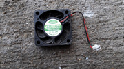


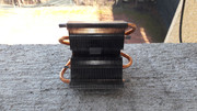
Waiting for some AC MX-4 TIM.
Also ready for some AC MX-4 TIM.

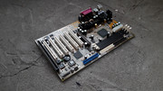
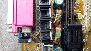
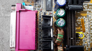
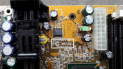
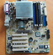
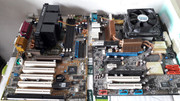
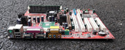
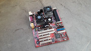
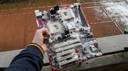
After I did my magic all of the problems and nagging things have been washed away and I was left with the most gorgeous piece of tech this side of the continent. 😁
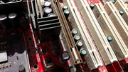
I took my sweet time and it showed. RED! IN YOUR EYES RED! SEE MEE RED! Good thing that the Fire Department folks weren't around as I am pretty sure that they would've hosed down my precious. 😁

I want to see MORE!


Totally worth it! Is all I could come up with when I took a hard long look at what I had accomplished. To some, this motherboard might not be a huge deal but to me it was a personal affair. It could've been another board but it happened to be this one. The rest is history.
What did we learn? You can perform a CPU socket "replacement" with basic tools and the all important common sense like I said earlier. Easy as pie. This goes to show that even if something seems stupid or pointless it doesn't necessarily mean that it is stupid or pointless.
I searched for something like the I described above in regard to the CPU socket replacement but I found nothing on the Internet so this means that it is a World Premiere?!?!? Maybe? I am a modest guy and I let my "work" do the speaking for me.
I still haven't gotten over how easy is to remove the plastic shell from the CPU socket. It is mind boggling. Also I never intended to replace the second CPU shell even if one hook is damaged. The rest are in great shape.
My data shows that this method can be applied to socket 7 CPU sockets and maybe other types but until I get to do it on other sockets, take this with a bucket of salt.
Think of how many board that have this exact type of damage, can be saved. I am a little sad of the many boards that I saw and I didn't buy due to this problem when the solution was so easy.
Now you know! Get out there and save some boards!
Merry Christmas everyone!

More later.