VOGONS


A couple of retros I'm working on.

Topic actions

Reply 320 of 452, by Vipersan

User metadata
Rank Oldbie
Rank
Oldbie
IanB wrote:
This appears to be the same problem you had with the T5200. I have a 64MB compact flash and looked into this a bit more. This h […]
Show full quote
Vipersan wrote:

..and yes it does boot just fine ..but does not run the 40mb Conor ..(DOS 5)
Hence missing operating system ..

This appears to be the same problem you had with the T5200. I have a 64MB compact flash and looked into this a bit more.
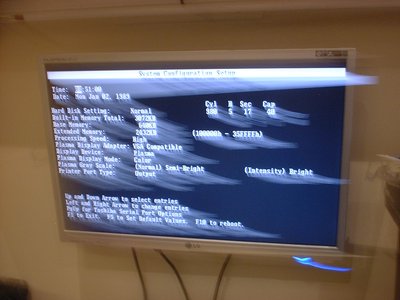
This has a native drive shape of 490 cylinders, 8 heads and 32 sectors per track as read directly from the CF but when the shape is read via the BIOS (in this case XTIDE) it comes back as 124 cylinders, 16 heads and 63 sectors per track. This amounts to about the same capacity (125440 sectors vs 124992 sectors) so will still give about the same storage but with a different geometry so my initial suspicion when we discussed this previously was correct. Those very small drives usually have 17 sectors per track so the geometry will definitely be translated to 63 sectors per track when connected via XTIDE.
I don't know if this behaviour with small drives is standard with all translating BIOSes or just a feature of XTIDE but reformatting and reinstalling should make it work again.

I guess it would but first I need to find a way to image the drive as I rather like the Dos 5 shell ..which I dont want to loose.
rgds
VS

Reply 321 of 452, by IanB

User metadata
Rank Member
Rank
Member
Vipersan wrote:

I've tried to represent what I believe to be the layout of the 9 chip simm with the solder bridge pads ..
normally open between 2 and 28

Yes the 9th chip is the parity and that has a separate CAS line (CAS9 on pad 28), the other 8 chips have a shared CAS line on pad 2. The T3200SX doesn't support the separate CAS9 line so the 9th chip also has to be connected to the shared CAS line.
i.e. You have to change the wiring so that pin 18 of the 9th chip also goes to pad 2 and pad 28 is left unconnected to anything. This probably involves making one of the solder bridge pads (to join the CAS9 line to the other CAS lines) and also cutting an already made link which may be on the other side of the SIMM (possibly under a chip!) to isolate pad 28.

Reply 322 of 452, by jaZz_KCS

User metadata
Rank Oldbie
Rank
Oldbie

Try the hybrid 03C and 03I bios from HighTreason, the same I use, it supports any drive as well as the original Connor drives. It defaults everything to 40 MB equal to the old Connor. So if you use more capacity as in CF or other adapters you need overlay software to get access. But with the hybrid BIOS your old Connor should also work fine. It also has the benefit of having the faster VGA bios from a later version 03I.

Last edited by jaZz_KCS on 2018-02-18, 22:27. Edited 1 time in total.

Reply 323 of 452, by Vipersan

User metadata
Rank Oldbie
Rank
Oldbie
IanB wrote:
Vipersan wrote:

I've tried to represent what I believe to be the layout of the 9 chip simm with the solder bridge pads ..
normally open between 2 and 28

Yes the 9th chip is the parity and that has a separate CAS line (CAS9 on pad 28), the other 8 chips have a shared CAS line on pad 2. The T3200SX doesn't support the separate CAS9 line so the 9th chip also has to be connected to the shared CAS line.
i.e. You have to change the wiring so that pin 18 of the 9th chip also goes to pad 2 and pad 28 is left unconnected to anything. This probably involves making one of the solder bridge pads (to join the CAS9 line to the other CAS lines) and also cutting an already made link which may be on the other side of the SIMM (possibly under a chip!) to isolate pad 28.

I suspected it might get tricky if the track cut is underneath a chip ..
Just my luck ..
doh!
thanks Ian

Reply 324 of 452, by Vipersan

User metadata
Rank Oldbie
Rank
Oldbie
jaZz_KCS wrote:

Try the hybrid 03C and 03I bios from HighTreason, the same I use, it supports any drive as well as the original Connor drives. It defaults everything to 40 MB equal to the old Connor. So if you use more capacity as in CF or other adapters you need overlay software to get access. But with the hybrid BIOS your old Connor should also work fine.

Thanks JZ ..
plenty to keep me occupied whilst I wait for the stuff I need to mod the 5200..
rgds
VS

Reply 325 of 452, by jaZz_KCS

User metadata
Rank Oldbie
Rank
Oldbie
Vipersan wrote:
Thanks JZ .. plenty to keep me occupied whilst I wait for the stuff I need to mod the 5200.. rgds VS […]
Show full quote
jaZz_KCS wrote:

Try the hybrid 03C and 03I bios from HighTreason, the same I use, it supports any drive as well as the original Connor drives. It defaults everything to 40 MB equal to the old Connor. So if you use more capacity as in CF or other adapters you need overlay software to get access. But with the hybrid BIOS your old Connor should also work fine.

Thanks JZ ..
plenty to keep me occupied whilst I wait for the stuff I need to mod the 5200..
rgds
VS

It also has the benefit of having the faster VGA bios from a later version 03I.

Reply 326 of 452, by IanB

User metadata
Rank Member
Rank
Member
Vipersan wrote:

I suspected it might get tricky if the track cut is underneath a chip ..

You need to make the link but you only need to isolate pad 28 with the cut if it's connected to something on the motherboard (like +5v or 0v) so maybe try measuring continuity of pin 28 of the SIMM slots to see if it has a path to ground or 5v. You could also try isolating that pad with some tape rather than cutting although the sharp edges of the SIMM pins might cut through it. If you have managed to isolate pin 28 some way but the memory still isn't detected then try making the other link to connect DP to QP.

Reply 328 of 452, by jaZz_KCS

User metadata
Rank Oldbie
Rank
Oldbie
IanB wrote:
jaZz_KCS wrote:

Try the hybrid 03C and 03I bios from HighTreason.

FYI the beta 3 BIOS is that version but with built in XTIDE and some other fixes.

In that case Vipersan, use that one 😁 You are even better off than me, then. Although I don't mind having to use overlay software to make use of the 2GB SD card.

Reply 329 of 452, by Vipersan

User metadata
Rank Oldbie
Rank
Oldbie
jaZz_KCS wrote:
IanB wrote:
jaZz_KCS wrote:

Try the hybrid 03C and 03I bios from HighTreason.

FYI the beta 3 BIOS is that version but with built in XTIDE and some other fixes.

In that case Vipersan, use that one 😁 You are even better off than me, then. Although I don't mind having to use overlay software to make use of the 2GB SD card.

If you like JZ ..I could flash another 1024 for you with the Beta 3 bios ..
let me know If you want one ?
it is the least I can do in light of your recent help with the Keyboard and Fdds.
rgds
VS

Reply 330 of 452, by IanB

User metadata
Rank Member
Rank
Member
Vipersan wrote:

I guess it would but first I need to find a way to image the drive as I rather like the Dos 5 shell ..which I dont want to loose.

I just tried connecting the 64MB CF card to a more modern PC (BIOS from 2004) and formatting it and that BIOS also translated the card's original 490 cylinders, 8 heads and 32 sectors per track to 124 cylinders, 16 heads and 63 sectors per track so it looks like XTIDE is behaving the same as modern BIOSes.

I did some further experiments and it looks like this may only cause problems with booting and you might be able to connect the small drive as a slave drive to a new larger drive (which you boot from) and copy the files off that way.

Reply 331 of 452, by Vipersan

User metadata
Rank Oldbie
Rank
Oldbie

So I nominated one simm strip as sacrificial
Connected one of the link pads which effectively connects pin 18 of the parity chip to the other 8 dram chips (pin 18) ie pin simm pin 2 ..CAS (bar)
all pin 18s connected together and to simm pin 2
..and then with a sharp knife point sliced through the trace connecting pin 28 of the simm ..thus isolating CAS9 (bar) from everything.
popped it into the 3200sx ...but sadly ..no change ?
So I'm wondering ...perhaps this simm is just not suitable for this mod ?
Pins 29 D9 and pin 26 Q9 are still connected to the parity chip of course ..but I assume this is ok ..
ah well ..cant win everything I suppose..

Attachments

  • DSCF0110.JPG
    Filename
    DSCF0110.JPG
    File size
    303.61 KiB
    Views
    616 views
    File license
    Fair use/fair dealing exception

Reply 332 of 452, by IanB

User metadata
Rank Member
Rank
Member
Vipersan wrote:

So I nominated one simm strip as sacrificial
Connected one of the link pads which effectively connects pin 18 of the parity chip to the other 8 dram chips (pin 18) ie pin simm pin 2 ..CAS (bar)
all pin 18s connected together and to simm pin 2

It's not clear from your post if you modded one simm or a pair of them as you have to fit them in pairs to be recognised because they are only 8 bits (+parity) and the bus is 16 bits wide.

Reply 334 of 452, by Vipersan

User metadata
Rank Oldbie
Rank
Oldbie
IanB wrote:
Vipersan wrote:

So I nominated one simm strip as sacrificial
Connected one of the link pads which effectively connects pin 18 of the parity chip to the other 8 dram chips (pin 18) ie pin simm pin 2 ..CAS (bar)
all pin 18s connected together and to simm pin 2

It's not clear from your post if you modded one simm or a pair of them as you have to fit them in pairs to be recognised because they are only 8 bits (+parity) and the bus is 16 bits wide.

Ahhh ..that might be the reason Ian ..
So far only modded 1 strip ..
I'll do another an try again.
😉
rgds
VS

Reply 335 of 452, by Vipersan

User metadata
Rank Oldbie
Rank
Oldbie
jaZz_KCS wrote:

Quite right! The additional RAM in both the 3200SX and 5200/100 have to be fit in (equal) pairs. You have to populate an entire "row" always.

Learning as I go JZ ..
will do another later and re-test
As you said in the other thread..
Welcome to the world of Toshiba
🤣

Reply 336 of 452, by Vipersan

User metadata
Rank Oldbie
Rank
Oldbie

I'm so glad I have you guys to talk to ..
Looking good ..
😁
sorry about the photo quality ..
I dragged the camera away too quickly after snapping.

I'll do 2 more strips tomorrow ..
I'm guessing there IS a pad under the 9th chip where a cut might be made ..but it is easier to cut right on simm contact 28.
So for Princeton Simms ..its link the pad provided and make one cut at pin 28

Attachments

  • DSCF0117.JPG
    Filename
    DSCF0117.JPG
    File size
    320.83 KiB
    Views
    598 views
    File license
    Fair use/fair dealing exception

Reply 337 of 452, by Vipersan

User metadata
Rank Oldbie
Rank
Oldbie

Modded 2 more this morning ..
I now have 04480k extended memory ..
which is nice
Damned shame I have an odd number of those Princeton simms..
I'll keep digging in boxes ...maybe ..just maybe there is a 6th lurking somewhere..
🤣
no luck so far ..but I did turn up an Avanced Micros Am486DX4-100 A80486DX4-100NV8T
When I'm dead my home will be a regular treasure trove for someone..
😉

Reply 338 of 452, by Vipersan

User metadata
Rank Oldbie
Rank
Oldbie

Another unexpected piece of retro just unconvered ..
A Velo 1 4mb with docking station ??
Such a tiny power connector I'm not sure I have anything to power it up and test it with ..
??
Some of this stuff hasn't seen the light of day in many years..

Attachments

  • DSCF0118.JPG
    Filename
    DSCF0118.JPG
    File size
    351.06 KiB
    Views
    576 views
    File license
    Fair use/fair dealing exception

Reply 339 of 452, by Vipersan

User metadata
Rank Oldbie
Rank
Oldbie

So ..I guess it does work ..
It will take 2 x standard AA batteries ...and I can see why it never really caught on..
Poor mono LCD image with backlight ..
running windows CE ..
rgds
VS

Attachments

  • DSCF0120.JPG
    Filename
    DSCF0120.JPG
    File size
    292.32 KiB
    Views
    574 views
    File license
    Fair use/fair dealing exception