VOGONS


Yet another 286 build.

Topic actions

Reply 120 of 171, by weedeewee

User metadata
Rank l33t
Rank
l33t
simon_e_hall wrote on 2022-07-04, 15:28:
Anyway back to the job in hand, mostly been playing with software and playing around on how I want the hard drive partitions set […]
Show full quote

Anyway back to the job in hand, mostly been playing with software and playing around on how I want the hard drive partitions set up on the 286.

However, also installed the extra 1mb RAM on the video card and again it did not recognise it, so installed the capacitors next to the banks, and passed continuity testing confirming they are likely required, but that did not work.

The extra RAM is connected to ET4000 confirmed through continuity testing.

There is a spot for a PAL chip (PAL16L8) so might install a socket and install a chip, now if that does not work there is only left spots for resistors and a VRM, but I have no clues of their values. I could a least see what the other capacitors are (100nF) to install the correct ones and the spot for the PAL chip states PAL16L8.

You do realize,i hope, that a pal16l8 chip is programmable logic, which means that the chip would need a specific program in order to function correctly for the purpose you require. Without that programming, nothing good will happen.

Right to repair is fundamental. You own it, you're allowed to fix it.
How To Ask Questions The Smart Way
Do not ask Why !
https://www.vogonswiki.com/index.php/Serial_port
Reply 121 of 171, by simon_e_hall

User metadata
Rank Member
Rank
Member
weedeewee wrote on 2022-07-04, 16:11:
simon_e_hall wrote on 2022-07-04, 15:28:
Anyway back to the job in hand, mostly been playing with software and playing around on how I want the hard drive partitions set […]
Show full quote

Anyway back to the job in hand, mostly been playing with software and playing around on how I want the hard drive partitions set up on the 286.

However, also installed the extra 1mb RAM on the video card and again it did not recognise it, so installed the capacitors next to the banks, and passed continuity testing confirming they are likely required, but that did not work.

The extra RAM is connected to ET4000 confirmed through continuity testing.

There is a spot for a PAL chip (PAL16L8) so might install a socket and install a chip, now if that does not work there is only left spots for resistors and a VRM, but I have no clues of their values. I could a least see what the other capacitors are (100nF) to install the correct ones and the spot for the PAL chip states PAL16L8.

You do realize,i hope, that a pal16l8 chip is programmable logic, which means that the chip would need a specific program in order to function correctly for the purpose you require. Without that programming, nothing good will happen.

Yes I do, been trying to map the pins this evening to see what they connect to maybe to figure out some possible options, long shot I know but it just interests me.

Reply 122 of 171, by Jo22

User metadata
Rank l33t++
Rank
l33t++
pshipkov wrote on 2022-06-19, 00:43:

Is there a proven fact that 287 fpu can run completelly async to cpu ?

Hi again, I know it's late, but I've kept searching for some documents and found something. 🙂

"[..] Additionally, older 286 boards were often configured to run the coprocessor at only two-thirds the speed of the CPU, making use of the ability of the 80287 to run asynchronously.
The 80287 has a CKM pin that causes the incoming system clock to be divided by three for the coprocessor if it is tied to ground. The 80286 always divides the system clock by two internally, hence the final ratio of 2/3.
However, when the CKM (ClocK Mode) pin is tied high on the 80287, it does not divide the CLK input.
This feature has been exploited by the maker of coprocessor speed sockets.
These sockets tie CKM high and supply their own CLK signal with a built-in oscillator,
thereby allowing the 80287 or compatible to run at a much higher speed than the CPU.

With an IIT or Cyrix 287, one can have a 20 MHz coprocessor running with a 8 MHz 80286. [..] "

Source: https://kb.iu.edu/d/aann

"Time, it seems, doesn't flow. For some it's fast, for some it's slow.
In what to one race is no time at all, another race can rise and fall..." - The Minstrel

//My video channel//

Reply 123 of 171, by simon_e_hall

User metadata
Rank Member
Rank
Member

Been a while since I have been on here, been busy with jobs around the house, but when I have chance been looking into the ET4000 as it interests me and the fact there is so little information about the board and the annoying fact that it has 2mb installed but only sees 1mb!

Put a socket in for the PAL chip and found a few blank ones which need programming. Been trying to see where the pins lead around the board.

Now I stress these are the initial and rough results at present, pins maybe 1 or 2 out as my eyesight is not the best looking at the small pins of the ET4000, but some seem to make sense:
Again I stress these are rough findings which I need to research further:

So using a PAL16L8ACN (as I had a few) as a guide:

PAL -> ET4000
------------

01 -> 51 (not sure about this connection)
02 -> NC
03 -> 48 (A<22:20>)
04 -> 47 (A<22:20>)
05 -> 46 (A<19:17>)
06 -> 45 (A<19:17>)
07 -> 44 (A<19:17>)
08 -> NC
09 -> 28 (IORC)
10 -> GND (as expected)
11 -> NC
12 -> 38 (BUSALE)
13 -> 73 (RDMH) (also to unpopulated Resistor 15, which in turns goes to Pins 31 (NC), 32 (P0) and 33 (P1) on the RAMDAC)
14 -> 15 (unsure)
15 -> 21 (unsure)
16 -> 27 (unsure)
18 -> NC
19 -> 29 (IOWC)
20 -> VCC (as expected)

Other things identified:

Unpopulated resistor 6 is on the VCC and connects to pin 42 (NC) on the RAMDAC, same with the unpopulated Voltage Regulator, so assess this was possibly for another type of RAMDAC, maybe...

Unpopulated resistor 18 connects to pin 25 (EBIO) on the ET4000, an odd one if it is correct connecting to pin 25, option to change BIOS location?

Unpopulated resistor 17 and 19 connect to nothing, or nothing found as of yet.

Reply 124 of 171, by simon_e_hall

User metadata
Rank Member
Rank
Member

In fact just sat down with a beer and had a thought, maybe I am overthinking this. It still bothers me it came with sockets, why do this if it cannot be upgraded, from a production cost it does not make any sense. What if the video BIOS is the problem and limited and a kit would have had a new BIOS? Might dump it later and dig around in it.

Reply 125 of 171, by Jo22

User metadata
Rank l33t++
Rank
l33t++

^Hi. The G540 EPROM programmer is said to have a PAL/GAL probing feature.
Ideally, it should be able to find out the "programming" of such a chip.
Not sure if that's helpful, though. 🙂

"Time, it seems, doesn't flow. For some it's fast, for some it's slow.
In what to one race is no time at all, another race can rise and fall..." - The Minstrel

//My video channel//

Reply 126 of 171, by pshipkov

User metadata
Rank Oldbie
Rank
Oldbie
Jo22 wrote on 2022-07-12, 14:51:
Hi again, I know it's late, but I've kept searching for some documents and found something. 🙂 […]
Show full quote
pshipkov wrote on 2022-06-19, 00:43:

Is there a proven fact that 287 fpu can run completelly async to cpu ?

Hi again, I know it's late, but I've kept searching for some documents and found something. 🙂

"[..] Additionally, older 286 boards were often configured to run the coprocessor at only two-thirds the speed of the CPU, making use of the ability of the 80287 to run asynchronously.
The 80287 has a CKM pin that causes the incoming system clock to be divided by three for the coprocessor if it is tied to ground. The 80286 always divides the system clock by two internally, hence the final ratio of 2/3.
However, when the CKM (ClocK Mode) pin is tied high on the 80287, it does not divide the CLK input.
This feature has been exploited by the maker of coprocessor speed sockets.
These sockets tie CKM high and supply their own CLK signal with a built-in oscillator,
thereby allowing the 80287 or compatible to run at a much higher speed than the CPU.

With an IIT or Cyrix 287, one can have a 20 MHz coprocessor running with a 8 MHz 80286. [..] "

Source: https://kb.iu.edu/d/aann

Yes, that's right. It was discussed previously in several threads.
Also, multiple tests have been performed by different members including me.
287 FPUs can tick at 2/3 rate, but still based on the same clock signal, while for a brief period of time a question was imposed here if the clock oscillator next to the FPU somehow magically puts it on a completely different sync signal, which was improbable but still ...

retro bits and bytes

Reply 127 of 171, by simon_e_hall

User metadata
Rank Member
Rank
Member
Jo22 wrote on 2022-07-12, 19:13:

^Hi. The G540 EPROM programmer is said to have a PAL/GAL probing feature.
Ideally, it should be able to find out the "programming" of such a chip.
Not sure if that's helpful, though. 🙂

Problem is the board came with no PAL on it, so I am trying to work out in reverse what the functions could have been and then program a chip accordingly, bit of a long shot though. However, intresting information you dug up previously.

Reply 128 of 171, by simon_e_hall

User metadata
Rank Member
Rank
Member

Well the BIOS idea sucks, seems to able to detect up to 4mb (which is the maximum for the chipset) and is a standard ET4000 BIOS by the looks of things. I have attached the BIOS just for information purposes.

Attachments

  • Filename
    C000.TXT
    File size
    32.32 KiB
    Downloads
    36 downloads
    File license
    Fair use/fair dealing exception

Reply 129 of 171, by simon_e_hall

User metadata
Rank Member
Rank
Member

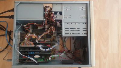
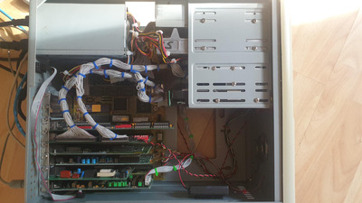
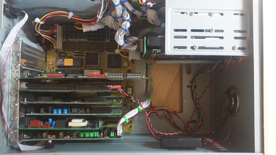
Nothing much going on but a bit of a tidy up and sort cables out, pretty poor quality photographs but the sun is getting in the way of every angle, who would have thought it in the UK!

Attachments

  • Cables_002.jpg
    Filename
    Cables_002.jpg
    File size
    230.42 KiB
    Views
    924 views
    File license
    Fair use/fair dealing exception
  • Cables_001.jpg
    Filename
    Cables_001.jpg
    File size
    292.12 KiB
    Views
    924 views
    File license
    Fair use/fair dealing exception

Reply 130 of 171, by maxtherabbit

User metadata
Rank l33t
Rank
l33t

The bundled scsi and floppy ribbons hurt my soul.

For ide it doesnt matter but both shugart and scsi are designed such that there is a ground wire interspersed between each signal line. If you want to round them it really ought to be twisted pair

Reply 131 of 171, by mR_Slug

User metadata
Rank Member
Rank
Member
maxtherabbit wrote on 2022-07-14, 21:55:

The bundled scsi and floppy ribbons hurt my soul.

For ide it doesnt matter but both shugart and scsi are designed such that there is a ground wire interspersed between each signal line. If you want to round them it really ought to be twisted pair

Not herd that doing this may interfere with signal quality. FWIW I have a full tower case with a floppy at the top connected via bundled cable that has been fine for years. But perhaps I may have thrown out some disks that didn't need to go.

I sometimes end up doing some complex origami with ribbon cables. Usually it is just a fold to go round 90 but sometimes it gets complex with trying to get a wide cable through a thin hole.

--

Nice 286 Rimmzy...Gazpacho Soup 😀

The Retro Web | EISA .cfg Archive | Chip set Encyclopedia

Reply 132 of 171, by simon_e_hall

User metadata
Rank Member
Rank
Member

Never had any issues as I usually use bundled/ rounded cables in my builds, probably because my chain of SCSI devices are usually limited in number and over a very short distance, so signal loss/ interference is not to bad. Think my cable thing is a hang up from the 90's (maybe early 2000's), when they were suppose to improve cooling and came in all sorts of colours and I thought looked cool and tidy.

However, what I do have in my cable collection is this DELL (or even Compaq) OEM twisted pair bundled cable, so I have installed that, it is a bit longer than the previous one but has an edge connector.

Attachments

  • Cables_003_Flip.jpg
    Filename
    Cables_003_Flip.jpg
    File size
    280.18 KiB
    Views
    886 views
    File license
    Fair use/fair dealing exception

Reply 135 of 171, by simon_e_hall

User metadata
Rank Member
Rank
Member

Presently 50mhz crystal for the 25mhz cpu, so in theory stock, going to source some other crystals to see about playing around with an overclock at some point.

NSSI reports
CPU 25MHz, real mode, 1/2/8/7
FPU 20MHz 3/3/3/5

CPU 4413 ~ 4441 Dhrystones
FPU 962 ~ 963 KWhetstones

Landmark reports
CPU clock 24.114 MHz
CPU at 32.67 ~ 32.99 MHz
FPU 26.70 ~ 26.95 MHz

Reply 136 of 171, by simon_e_hall

User metadata
Rank Member
Rank
Member

Been a slow week and mostly be tweaking system options which has raised some issues with the chipset.

1) Thought that I had sorted out with random freezes, which I thought was due to the IDE controller as it always happened at heavy load or testing, but it came back. The only thing different was that I enabled the shadowIng of the video and BIOS, which appears to be the issue as when it is disabled the issues go away and when enabled the fault can be replictated.

Of course all testing was done without any memory manager installed.

2) The other issue I have found is that enabling the Fast A20 gate option causes the system to freeze just as the operating system loads, cannot even press F5/ F8, so before config.sys is loaded.

I can't help that think there is more to the shadow RAM issue, such as those damn jumpers at the top of the board that have something to do with RAM configurations as the EMS driver now does not work. However, all tests I do on the RAM pass so going to search the net when I get chance to find a datasheet for the HT18 if I can and then continue to trace the jumpers to the chipset.

Thought this would be a nice simple build, but there is a few little issues still to iron out, before I move onto the next stage or installing a new BIOS and attempting to push the hardware a little bit.

Reply 138 of 171, by simon_e_hall

User metadata
Rank Member
Rank
Member
mR_Slug wrote on 2022-07-20, 14:37:

Thanks, I got distracted reading through your chipset encyclopedia page until I saw your post update, will get my meter out at some point and start trying to figure the jumpers out, once again thank you.

Reply 139 of 171, by pshipkov

User metadata
Rank Oldbie
Rank
Oldbie

Too bad stability issues are striking again.
We went over it once or twice already in previous posts, but again - i am confident that the jumper settings you used as a reference from the picture i provided are correct and work really well with all settings on max, maxed-out RAM, 0-waits and 25-30MHz frequency range.
Good chance you have flaky RAM modules.

retro bits and bytes