Reply 320 of 434, by rknize
Eivind wrote on 2024-01-11, 18:14:So... reading your comments and thinking about this, I suspect the ferrite bead FB8 is either broken or not making good contact […]
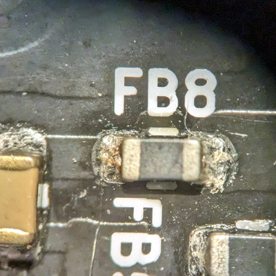
So... reading your comments and thinking about this, I suspect the ferrite bead FB8 is either broken or not making good contact with its pads.
First of all - the ferrite bead itself should only drop the voltage a miniscule amount, like 0.01V in my measurement. The fact that you're both not seeing any voltage there when there's no AGP card inserted, and a drop of 0.2V when there is looks to me like that rail "VCC_3V3_AGP" is being backfed from the other 3.3V AGP rail, the "VCC_VIO_AGP" through the card itself. Which is definitely not good, but might explain the card-dependant erratic behavior you're seeing - as these are supposed to be separate rails providing power to the card.
I'll attach a screenshot of the AGP schematic here for now.Using a voltmeter, try measuring resistance through the ferrite bead, and play around with touching either the bead leads themselves, or the tiny pads it's attached to.
You could also try desoldering the FB8 bead and bridging the gap with solder directly.
That's so funny that I would write all that and not realize that there should never be any voltage across a ferrite bead. I guess because all SMD stuff looks the same, I forgot that it's just a jumper with a bead around it, 🤣. That's what happens to an EE that's done software his entire career. That has to be the issue. I'll give it a try later today...thanks for the schematic fragment. I'll remove the cap on the ATT, since that is obviously not related.