VOGONS


Reply 420 of 474, by valterb

User metadata
Rank Newbie
Rank
Newbie

My motivation for wanting Nvidia cards to work is purely the fact that ATi cards of that era have some issues in DOS and there aren't any low-profile AGP Voodoo cards (that I know of), rather than performance. At this point I'm probably just going to settle with using my Voodoo 3 in a thicker case or with a riser cable.

Also, Eivind, the newer firmware for the MCU is still working okay for me with the one exception being that the setting for the power LED keeps getting reset. Out of curiosity, would it be possible for you to include that firmware to the Github repo? The BIOS code would be nice too.

Last edited by valterb on 2024-03-27, 18:24. Edited 1 time in total.

Reply 421 of 474, by Dothan Burger

User metadata
Rank Newbie
Rank
Newbie
ahmadexp wrote on 2024-03-27, 06:00:

Alright, so I was able to pack everything (ITX llama, Voodoo 3000 and a SATA) in the mini ITX case (bought off ebay and attached the picture).
To do that, I had to use an AGP riser from MODDIY. But man, that was then the nightmare began. With the riser I was unable to get the card working. Then I looked into the signal condition that was causing the issue. So, I shortened the cable to the size that I wanted and soldered all the wires back. That did not help of course and I still did not have the card working. Then I cleaned the cable to have the solder residue removed. That made the card work but it was not stable. Then I wrapped the cable with copper tape (also between the the ribbon cables) and finished it off with Kapton tape. That did the magic and everything is working very well. I had build a custom IO shield and have everything nicely put together. I have two Noctua fans ready to be placed to make the entire thing look amazing. Here is a sneak peek.

I love this setup. You truly have created something special here my guy. It fits with what I feel the whole principle of this build should be.

Would you mind sharing the name of the case you used? If not that's cool

Do you think the AGP riser would work without shortening it? I just don't have the skill to do all that soldering without spazzing out and ripping something.

Reply 422 of 474, by ahmadexp

User metadata
Rank Newbie
Rank
Newbie
Dothan Burger wrote on 2024-03-27, 18:00:
I love this setup. You truly have created something special here my guy. It fits with what I feel the whole principle of this […]
Show full quote
ahmadexp wrote on 2024-03-27, 06:00:

Alright, so I was able to pack everything (ITX llama, Voodoo 3000 and a SATA) in the mini ITX case (bought off ebay and attached the picture).
To do that, I had to use an AGP riser from MODDIY. But man, that was then the nightmare began. With the riser I was unable to get the card working. Then I looked into the signal condition that was causing the issue. So, I shortened the cable to the size that I wanted and soldered all the wires back. That did not help of course and I still did not have the card working. Then I cleaned the cable to have the solder residue removed. That made the card work but it was not stable. Then I wrapped the cable with copper tape (also between the the ribbon cables) and finished it off with Kapton tape. That did the magic and everything is working very well. I had build a custom IO shield and have everything nicely put together. I have two Noctua fans ready to be placed to make the entire thing look amazing. Here is a sneak peek.

I love this setup. You truly have created something special here my guy. It fits with what I feel the whole principle of this build should be.

Would you mind sharing the name of the case you used? If not that's cool

Do you think the AGP riser would work without shortening it? I just don't have the skill to do all that soldering without spazzing out and ripping something.

Thank you for your words. Of course I will share the case. Here is the link: https://www.ebay.ca/itm/355147325878
and here is where I got the riser: https://www.moddiy.com/products/AGP-16X-8X-Ex … Riser-15cm.html

I think you probably need to go the copper shielding to get it work. I believe, you should give it a try. Worst case I will try my best to help you.

And here is a picture of the IO panel.

Attachments

Reply 423 of 474, by ahmadexp

User metadata
Rank Newbie
Rank
Newbie

Also, in case anyone likes a proof that this is working, I attached more pictures. I also attached a picture of how much of that cable I had to trim.

Attachments

Reply 424 of 474, by Dothan Burger

User metadata
Rank Newbie
Rank
Newbie
ahmadexp wrote on 2024-03-27, 21:42:

Also, in case anyone likes a proof that this is working, I attached more pictures. I also attached a picture of how much of that cable I had to trim.

That's an interesting idea to have it come out the I/o shield, I like it.

I've never used a Pico power supply before. Do I need to use an AC adapter that matches the same max output of the Pico power supply? I have plenty of 12v adapters that should cut it for this system but aren't up to the max spec of the Pico.

Reply 425 of 474, by ahmadexp

User metadata
Rank Newbie
Rank
Newbie
Dothan Burger wrote on 2024-04-02, 04:23:
ahmadexp wrote on 2024-03-27, 21:42:

Also, in case anyone likes a proof that this is working, I attached more pictures. I also attached a picture of how much of that cable I had to trim.

That's an interesting idea to have it come out the I/o shield, I like it.

I've never used a Pico power supply before. Do I need to use an AC adapter that matches the same max output of the Pico power supply? I have plenty of 12v adapters that should cut it for this system but aren't up to the max spec of the Pico.

I am using a 12v 2A generic wall plugged adapter and it works fine. I doubt you will have any issue as long as it gives enough power.
Also, I have been looking to modify the front panel to add the OLED for the MT32. Let's see that comes out.

Reply 426 of 474, by ahmadexp

User metadata
Rank Newbie
Rank
Newbie

Here are the results from modifying the front panel to host the OLED display for the MT32-Pi

Attachments

Reply 427 of 474, by tabm0de

User metadata
Rank Member
Rank
Member
ahmadexp wrote on 2024-04-09, 15:27:

Here are the results from modifying the front panel to host the OLED display for the MT32-Pi

Nice , going to do something similar, but also add buttons to be able to switch btw gm and Roland mt32 😀

naa, nothing yet...

Reply 428 of 474, by ahmadexp

User metadata
Rank Newbie
Rank
Newbie
tabm0de wrote on 2024-04-09, 15:32:
ahmadexp wrote on 2024-04-09, 15:27:

Here are the results from modifying the front panel to host the OLED display for the MT32-Pi

Nice , going to do something similar, but also add buttons to be able to switch btw gm and Roland mt32 😀

Yeah, I thought about doing that in a clean way. Then I came up with a touch based method were you touch the bezel of the OLED as a button. I still did not get it work.

Reply 429 of 474, by Dothan Burger

User metadata
Rank Newbie
Rank
Newbie
ahmadexp wrote on 2024-04-09, 16:06:
tabm0de wrote on 2024-04-09, 15:32:
ahmadexp wrote on 2024-04-09, 15:27:

Here are the results from modifying the front panel to host the OLED display for the MT32-Pi

Nice , going to do something similar, but also add buttons to be able to switch btw gm and Roland mt32 😀

Yeah, I thought about doing that in a clean way. Then I came up with a touch based method were you touch the bezel of the OLED as a button. I still did not get it work.

Nice! it would be kind of neat if it could show a midi tracker.

Has anyone used the ESP8266 module? How do you use it?

Reply 430 of 474, by snipe3687

User metadata
Rank Newbie
Rank
Newbie

Hey guys I need your help. I built my ITX llama and everything seems to be working except anything connected to the ATTINY. I checked all my solder connections and everything seems to be fine. the LED is soldered in correctly and I can trigger it with my meter when I'm testing voltage on the pins. pins 1-7 on the ATTINY have 3.3v but on the other side only pin 9 has voltage. I already flashed the BIOS on the SOM so the system works in that sense. I checked the i2c lines but they have continuity and it even is able to read the fan controller so I know that works. In my frustration I pulled the ATTINY and replaced it with another one but have the same problem. I pulled the chip and read it in my EEPROM programmer and it's showing as blank. I don't know if it should have data on it or not but clearly I'm missing something.

ANY HELP WOULD BE MUCH APPRECIATED! 😀

Reply 431 of 474, by tabm0de

User metadata
Rank Member
Rank
Member
snipe3687 wrote on 2024-05-08, 02:50:

Hey guys I need your help. I built my ITX llama and everything seems to be working except anything connected to the ATTINY. I checked all my solder connections and everything seems to be fine. the LED is soldered in correctly and I can trigger it with my meter when I'm testing voltage on the pins. pins 1-7 on the ATTINY have 3.3v but on the other side only pin 9 has voltage. I already flashed the BIOS on the SOM so the system works in that sense. I checked the i2c lines but they have continuity and it even is able to read the fan controller so I know that works. In my frustration I pulled the ATTINY and replaced it with another one but have the same problem. I pulled the chip and read it in my EEPROM programmer and it's showing as blank. I don't know if it should have data on it or not but clearly I'm missing something.

ANY HELP WOULD BE MUCH APPRECIATED! 😀

I think firmware for sound and usb to ps2 are not apart of the github, i might be that Eivind missed to add them.

naa, nothing yet...

Reply 432 of 474, by snipe3687

User metadata
Rank Newbie
Rank
Newbie
tabm0de wrote on 2024-05-08, 07:49:
snipe3687 wrote on 2024-05-08, 02:50:

Hey guys I need your help. I built my ITX llama and everything seems to be working except anything connected to the ATTINY. I checked all my solder connections and everything seems to be fine. the LED is soldered in correctly and I can trigger it with my meter when I'm testing voltage on the pins. pins 1-7 on the ATTINY have 3.3v but on the other side only pin 9 has voltage. I already flashed the BIOS on the SOM so the system works in that sense. I checked the i2c lines but they have continuity and it even is able to read the fan controller so I know that works. In my frustration I pulled the ATTINY and replaced it with another one but have the same problem. I pulled the chip and read it in my EEPROM programmer and it's showing as blank. I don't know if it should have data on it or not but clearly I'm missing something.

ANY HELP WOULD BE MUCH APPRECIATED! 😀

I think firmware for sound and usb to ps2 are not apart of the github, i might be that Eivind missed to add them.

That's my thought as well! My gut was telling me that I needed to flash something on it but I'm a noob at this stuff still, so I thought there was a chance I missed something and maybe the BIOS flash also covered the ATTINY.

I found a firmware he posted for someone to test a while back for the ATTINY but when I tried it the only thing that happened was now the red LED is blinking non-stop. still can't enable the LED or clicker in the BIOS.

Eivind: if you read this, could you PLEASE post the firmware for the ATTINY and the RP2040 somewhere? I really appreciate what you do!

On a side note:
I've built 2 tinyLlamas so far and am hoping to have similar success with this project as well!

Reply 433 of 474, by snipe3687

User metadata
Rank Newbie
Rank
Newbie
Eivind wrote on 2024-02-07, 09:07:
First of all - I just updated the github page with complete schematics, layouts and gerbers, so you're all free to follow along. […]
Show full quote
Aaron707 wrote on 2024-02-07, 01:24:

So my board has been working good and I was trying out some games. The machine was on screen saver then the screen possibly went to sleep when I was doing something else. I tried to wake it but couldn't get any display. So powered it off and back on, still no display. Tried a different GPU, same. Reading about a similar issue earlier in this thread I checked FB8 and it was getting 3.3V on only one side. So removed it and jumpered FB8 (removing the FB it fell apart). Tested again and got some magic smoke (see picture below of bottom of board). Hopefully its not ruined. Pretty sad this happened. Is that burnt trace the ground plane? the side closer to socket measures shorted to ground. And the side of FB8 further from the slot of measures 468ohms to ground . And somehow R30 right next to AGP slot was turned sideways and fell off when touched. What is the value of R30? Any ideas what to check or why I lost video would be greatly appreciated. I think I will set this project aside for today and come back to it later this week with a clear head.

First of all - I just updated the github page with complete schematics, layouts and gerbers, so you're all free to follow along.

Then, to you issue Aaron, the trace that fried is part of the "VCC_3V3_AGP" net - one of two 3.3V power rails going to the AGP slot. The reason it was destroyed is almost certainly a dead short to ground - which if I understand you correctly is what you measured as well. Looking at your photo, I'd venture a guess and say that the short is somewhere really close to the fried area, as that trace is actually thicker right there than at some other places on the same net. If the short was farther away, the thinnest part of the net would likely have melted.

Try removing the AGP card from the slot (to keep VCC_3V3_AGP and VCC_VIO_AGP separated) and locate the point where the burnt trace shorts to ground - that's a good place to start at least.

Not sure why R30 loosened and fell off, might have been desoldered by the heat caused by the short? The (partial?) short probably happened first, then the FB8 was ruined by the increased current, and when you bridged the FB8 footprint, the current melted the trace.

If nothing else was destroyed, if you're able to locate and fix the short and then solder on a good-thickness wire in place of the broken trace, you should hopefully be good to go. Fingers crossed! 😀

Lastly, I don't yet understand why you got the short in the first place - hopefully we'll get to the bottom of this!

possible to get the firmware for the ATTINY and RP2040 posted too?? PLEASE 😉

Reply 434 of 474, by snipe3687

User metadata
Rank Newbie
Rank
Newbie

quick update to my previous posts, Using the firmware for the ATTINY that was posted back in January on this thread I was able to get the power, HDD, clicker, etc. working. I was missing the low and high fuse values - something I didn't know anything about until working on this last night. I had some other minor issues with things like the SD card not being detected and hanging the system and the RP2040 not showing up as a USB device when connected to a windows PC, but I was able to sort those out as well. The SD card lines were bridged in 1 spot on the SOM header so reflowing solved that and same problem with the RP2040 but had to reflow the chip itself. still need firmware for that though!

Now I'm having a problem with the sound chip.
I noticed the S/PDIF port wasn't lit up so did some investigating. it's getting 5v where it should be on the line driver and there's continuity from the S/PDIF line on the CS4237 chip. I dug more into it, and I actually have no sound at all. The BIOS message says CS4237B Initialized on POST but cwdinit.exe says no crystal device detected even after inputting the environmental variables - SET BLASTER=A220 I7 D1 P330 T4. I tried UNISOUND to see if it finds the card, but it says no PNP devices detected - yes, I know the card should be initialized by the BIOS meaning no need for UNISOUND, but I had to try for my own sanity.

I checked over the pins on the chip and they are all solidly soldered to the board. Checked the pinout of both the chip and the board and found all locations that should have power and they all are getting their correct values.
Checked that the chip was oriented correctly as I've messed that up on another project in the past and it is indeed correct.

I also checked continuity on all the address lines and traced them back to the SOM. they all tested good. I didn't check A12 or A14 yet as they are on the other side of the SOM's header and didn't have time to pull it this morning, but I will later. I'm thinking they are probably ok though. Same with IRQ (IRQ7) and DMA (both DRQ1 and DACK1) lines. all seem to have continuity back to the SOM. also checked for bridges between all 100 pins and their neighbors.

Once again, I have to ask, AM I MISSING SOMETHING???
I know on the tinyLlama you had to flash an EEPROM to get it to work but that should be handled by the BIOS now as there is no EEPROM anymore, so I don't know what else to check. I'll check A12 and A14 tonight when I get home from work but the only other idea I have is to reflow all the chip legs, even though they have continuity, or replace the chip outright. It seems unlikely it's bad as it was brand new....well, NOS and never opened.

any CS4237B experts out there have any ideas?
What are the absolute bare minimum connections that the chip needs to be detected by DOS? I'm guessing address, data, IRQ and DMA lines and power but I certainly could be wrong!
If something was bridged on the input/output side like the wavetable header or even the speaker jacks on the back, could that cause the card to go into a protection mode or something?
I really just need to know WHERE to go next!

 Aside from the RP2040 firmware, this is the last big issue I'm facing with my ITX llama build!

Reply 435 of 474, by Deksor

User metadata
Rank l33t
Rank
l33t

Did you flash the firmware to the crystal chip? I remember that I had to do it on the tinyllama 1.1

Trying to identify old hardware ? Visit The retro web - Project's thread The Retro Web project - a stason.org/TH99 alternative

Reply 436 of 474, by Eivind

User metadata
Rank Oldbie
Rank
Oldbie

Shit I'm sorry I didn't catch this earlier - you're right I forgot to put the rp2040 and attiny sources on the github repo! I haven't been playing around much with the itx board lately because of other projects stealing my brain power... 😀
I'll update the repo!
As for the CB4237B - to get digital output you have to enable that in the BIOS settings. But since you're apparently not getting audio at all, that seems to point to either a faulty chip or improper soldering. I've had first hand experience with having to do multiple rounds with the iron over all the pins to get perfect contact. The chip can be quite fiddly to get exactly right. And - unfortunately it can also be bricked if you're not careful (which I've also done).

The LlamaBlaster sound card
ITX-Llama motherboard
TinyLlama SBC

Reply 437 of 474, by Eivind

User metadata
Rank Oldbie
Rank
Oldbie
Deksor wrote on 2024-05-09, 20:08:

Did you flash the firmware to the crystal chip? I remember that I had to do it on the tinyllama 1.1

There's no CS4237B eeprom/firmware for the itx board - the chip is programmed directly during POST, using the values set in the BIOS settings.

The LlamaBlaster sound card
ITX-Llama motherboard
TinyLlama SBC

Reply 438 of 474, by Eivind

User metadata
Rank Oldbie
Rank
Oldbie
snipe3687 wrote on 2024-05-08, 15:00:

possible to get the firmware for the ATTINY and RP2040 posted too?? PLEASE 😉

It's on github now! 😁

The LlamaBlaster sound card
ITX-Llama motherboard
TinyLlama SBC

Reply 439 of 474, by snipe3687

User metadata
Rank Newbie
Rank
Newbie
Eivind wrote on 2024-05-09, 23:15:
snipe3687 wrote on 2024-05-08, 15:00:

possible to get the firmware for the ATTINY and RP2040 posted too?? PLEASE 😉

It's on github now! 😁

Awesome, thank you so much!

So last night I went through the entire board again. Checked the datasheet for the CS4237b, found all the pins and where they go on the board and verified, they all have continuity. After that I went through and reflowed every pin again, checked for continuity between the pins as well as poked them all with the fine tip leads of my meter to make sure nothing was loose. Still nothing at power on. After that I decided to bite the bullet and I removed the chip completely from the board, cleaned everything really well and then put a brand-new chip on the board. same process as before, soldered everything and checked all the pins really well, no continuity between any pins and they are all securely soldered, so I booted it up and STILL nothing!
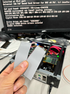
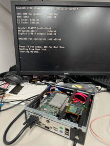
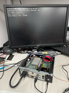
I did power on the board with the chip removed to see if anything in the POST or BIOS changed because one thing I noticed before in the BIOS that the setting to enable the external synth module is disabled and greyed out. Same thing with the chip out of the board so that leads me to believe the BIOS is not reading the CS4237b to be able to toggle. I would assume you could do that even without an external synth since I don't have one and my understanding is it's just a chip select line that is being enabled. It also helped me verify that the "CS4237b initialized" message is a static string of text and doesn't actually tell me that anything is really initialized like the PWM fan controller does. (if I'm wrong let me know!)

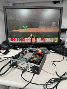
Next, I decided to install windows 98 to see if the chip is detected there to see if maybe the codec is working but it wasn't detected at all.
I have to be missing something.
I noticed when I set the blaster variable: SET BLASTER=A220 I7 D1 P330 T4 and run CWDMIX.EXE I get this message:

Illegal function call in line 0 of module SBMIXER at address 0703:00F2
I did see this before with the other part too but didn't think much of it. Is this a problem with the chip or CWDMIX?

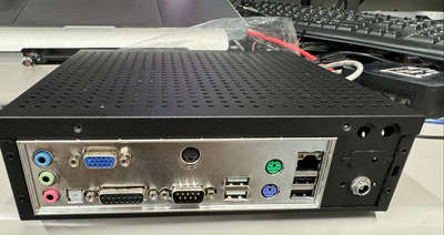
My next step was to remove items from the board that weren't required for the chip to be seen by the SOM. I removed the line driver for the S/PDIF and the op amp but again, no life. At this point I don't know what to check. I plan to go over all the passives later with my meter and verify they are reading the correct values. I was VERY religious about following the BOM during assembly and was checking each part off as I was installing them but maybe I goofed up. other than that, I also plan to disconnect any lines running to non-critical items like the line to the PI, the header for the wave table and external synth.

Is it possible it's stuck in reset somehow? I see the reset line goes to U2 which connects the reset line between the SOM, CS4237b and the PCIe to PCI bridge chip but I didn't think much of that since the bridge chip is working although, funny story, I had a passive on the bridge chip not quite soldered down and when I first powered the board it blew out the original bridge chip. it was getting 3.3v on the 1.15v line from U7. I'm wondering if it's possible that U2 is holding the RSTDRV line high keeping the chip from enabling. I'll have to check that with my scope. I noticed on the datasheet it says if the line is driven high, it will put the chip in low power mode so maybe that's my problem? I did scope all the address and data lines and saw activity so maybe that's not the case but who knows, maybe it should be sending and receiving data on the address/data lines in low power but then why wouldn't it be detected? IDK!

My other thought was to compare the address and data signals to the ones my TinyLlama v2 has since I know that one works. I tried the SOM from the TinyLlama v2 on the ITX since there's nothing in it that initializes the CS4237b but again...SAME THING...ugh.

any and all suggestions are VERY MUCH appreciated!

Also, Eivind, do you have gerbers for the OPL3 module somewhere? I'd love to build one of those too! I already bought the chips based on studying your images 😀

as always THANK YOU!