VOGONS


Tiny 486 build - SBC with ISA backplane

Topic actions

Reply 20 of 76, by megatron-uk

User metadata
Rank Oldbie
Rank
Oldbie

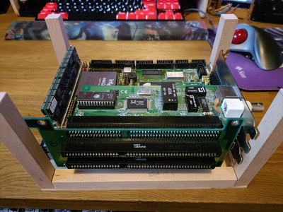
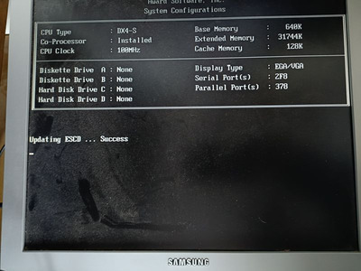
Just rigged up a quick and dirty test environment with a shorted PS_ON pin on the Pico PSU and an ancient Samsung VGA LCD I had in the attic. Using the 3.5" FDD power cable from the Pico PSU direct to J1 on the SBC:

img20240303090734.jpg
Filename
img20240303090734.jpg
File size
102.43 KiB
Views
723 views
File license
CC-BY-4.0
img20240303090728.jpg
Filename
img20240303090728.jpg
File size
69.72 KiB
Views
723 views
File license
CC-BY-4.0
img20240303090848.jpg
Filename
img20240303090848.jpg
File size
70.14 KiB
Views
723 views
File license
CC-BY-4.0

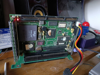
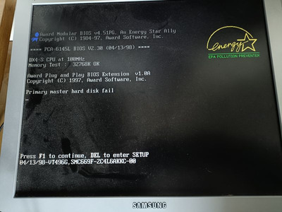
PS/2 keyboard directly attached to the keyboard connector responds okay.
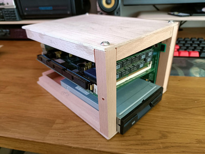
All seems to work fine. The BIOS had retained values, but (the battery) is soldered on, so that may be something to resolve before building the case around it.

My collection database and technical wiki:
https://www.target-earth.net

Reply 21 of 76, by megatron-uk

User metadata
Rank Oldbie
Rank
Oldbie
megatron-uk wrote on 2024-03-03, 08:33:

Although, now digging deeper, the waveblaster header specifies a -12v DC voltage on pin 22.... this would mean that this card technically doesn't meet the requirements of hosting a waveblaster daughterboard.

I only have a NEC XR385 (which I won't be using - far too big), but am planning on getting a WP32 McCake in the near future. I'm wondering if that would actually need the -12v line...

Just heard from Serge at Serdashop; the WP32 design only uses the +5v voltage connections in the waveblaster connector; both +12 and -12 are not required. As long as there is enough juice from that J1 connector on the SBC, that means I shouldn't need to connect any additional wiring from the main ATX plug in the Pico PSU (other than extending PS_ON to a front panel button/switch).

My collection database and technical wiki:
https://www.target-earth.net

Reply 22 of 76, by SScorpio

User metadata
Rank Member
Rank
Member
megatron-uk wrote on 2024-03-03, 08:27:

On the other hand, with the ESS ES1868F sound card, whilst B07 / -12v is missing, it does have a pad for B05 / -5v. However, there are a lot of missing, optional components on this card and I see no amplification circuitry of any kind - there is just the ES1868F chip, an oscillator, some electrolytics and a small handful of (i think?) inductors. The card also doesn't have a labelled speaker out (just line out).

Are you sure? From the images, it looks like you have both B05/-5V and B07/-12V but are missing B06/IRQ2 which makes sense. You then have a blank for B08/Waitstate and populated B09/+12V and B10/Ground that goes into a large ground plane on the back.

From the front, there are caps in the way on your image. But by the C15 + labeling there is a via which looks like it might be for the -12V, the -5V via should be around there but I can't see it. But it probably around the C16 cap.

Reply 23 of 76, by megatron-uk

User metadata
Rank Oldbie
Rank
Oldbie

Yeah, those 'off by one' errors really add up; you're correct.

The bigger problem I'm having right now is that I can't get it to boot from any floppy (which I need to do in order to check both the network card - and set the bootrom, and the sound card).

Two drives (both working), two cables (both pulled from working systems), and two working disks (1x 6.22 and 1x Win98 SE). All combinations returning 'disk i/o error'. Floppy seek at power on is good, no FDC errors during post. Attempts to boot from the disk, then throws the disk io error.

My collection database and technical wiki:
https://www.target-earth.net

Reply 24 of 76, by megatron-uk

User metadata
Rank Oldbie
Rank
Oldbie

It's the FDD header - looking at the pins they are quite tarnished (I guess to be expected based on the probable environment this has been working in).

I've scraped the pins with a thin hobby knife just to expose some fresh metal and I've gotten a Win 98SE floppy to boot. I'll probably have to do that properly, and give the IDE header pins a similar clean.

My collection database and technical wiki:
https://www.target-earth.net

Reply 25 of 76, by megatron-uk

User metadata
Rank Oldbie
Rank
Oldbie

I can confirm that the NIC works on the backplane - it's detected by Plug & Play bios, and the Realtek RSET8019.EXE utility detects the card and let me configure it (to enable an XT-IDE ROM). XT-IDE BIOS now shows on boot.

Next test it to put unisound on a floppy and see if the soundcard also works.

My collection database and technical wiki:
https://www.target-earth.net

Reply 26 of 76, by megatron-uk

User metadata
Rank Oldbie
Rank
Oldbie

Now booting from CF card via XT-IDE bios successfully.

Initial run from speedsys with empty config.sys and all of the obvious 'performance' options in the bios turned on:

IMG_20240303_184110_(1200_x_900_pixel).jpg
Filename
IMG_20240303_184110_(1200_x_900_pixel).jpg
File size
244.92 KiB
Views
658 views
File license
CC-BY-4.0

The current config of the board is:

Intel DX4-100
32MB 60ns EDO SIMM
128k onboard cache (12ns parts)

As expected for such a design, there aren't loads of tuning options.

It will ultimately be replaced by an AMD X5-133 and a 64mb EDO SIMM once I've got everything built around the backplane.

My collection database and technical wiki:
https://www.target-earth.net

Reply 27 of 76, by megatron-uk

User metadata
Rank Oldbie
Rank
Oldbie

Got the McCake board this week. Thanks to those involved for that. I think that completes the necessary set of major components.

I'm on building the inner frame of the case now - top and bottom are 215 x 150mm Maple panels, corners and sides reinforced with glued on 15x15mm hardware batons. One 'side' will be fastened on with stainless, dome headed allen bolts, so that it can be removed to take the ISA cards out.

Cut outs will be needed in the front panel for the floppy drive and a CF slot. I think I have some miniature stainless toggle switches in my box of bits for power and turbo switches. Unsure what to do with the reset function yet - ideally I'd have a matching momentary toggle switch, but all the switches I have are latching.

My collection database and technical wiki:
https://www.target-earth.net

Reply 28 of 76, by SScorpio

User metadata
Rank Member
Rank
Member
megatron-uk wrote on 2024-03-16, 11:12:

Cut outs will be needed in the front panel for the floppy drive and a CF slot. I think I have some miniature stainless toggle switches in my box of bits for power and turbo switches. Unsure what to do with the reset function yet - ideally I'd have a matching momentary toggle switch, but all the switches I have are latching.

Depending on the look you're going for, you could get a big red button that has a flip open plastic cover like a missile launch control panel. But in all honestly, toggle can work just fine. Sure it's not press and release, but flipping it on and off isn't a major hassle. And it requires more to engage versus a momentary switch.

Reply 29 of 76, by megatron-uk

User metadata
Rank Oldbie
Rank
Oldbie

Have the basic structure of the enclosure now made:

frame.jpg
Filename
frame.jpg
File size
204.04 KiB
Views
523 views
File license
CC-BY-4.0

Top, bottom and (one fixed, and one removeable) side panels now in place:

open_side1.jpg
Filename
open_side1.jpg
File size
131.14 KiB
Views
523 views
File license
CC-BY-4.0
open_side2.jpg
Filename
open_side2.jpg
File size
159.16 KiB
Views
523 views
File license
CC-BY-4.0
front.jpg
Filename
front.jpg
File size
133.95 KiB
Views
523 views
File license
CC-BY-4.0

With the side panel fitted:

panel_on.jpg
Filename
panel_on.jpg
File size
119.58 KiB
Views
523 views
File license
CC-BY-4.0

Next up is making some slight modifications to the ISA backplane/riser. I need to cut off one oddly-shaped corner, and drill another mounting hole in the ground plane so that I have 3 evenly spaced holes to use. This will be fitted to the 'fixed' side panel with some allen bolts and hexagonal spacers.

The part I'm not looking forward to is making the cut-outs in the front panel for the floppy, CF and switches. Then sand the whole thing down and try to put some nice bevelled edges on with a mini router I recently bought.... I might try that on some scrap pieces first though! 😁

My collection database and technical wiki:
https://www.target-earth.net

Reply 30 of 76, by megatron-uk

User metadata
Rank Oldbie
Rank
Oldbie

Backplane now mounted to the case:

backplane1.jpg
Filename
backplane1.jpg
File size
166.07 KiB
Views
496 views
File license
CC-BY-4.0

... and with ISA cards installed:

backplane2.jpg
Filename
backplane2.jpg
File size
240.33 KiB
Views
496 views
File license
CC-BY-4.0

The mounting holes on the backplane will need cleaning back a little so that there's no chance of anything conductive shorting to the bolts around the two additional holes I had to drill. Nothing a little dremel can't fix.

Next up will be the front panel.

My collection database and technical wiki:
https://www.target-earth.net

Reply 31 of 76, by megatron-uk

User metadata
Rank Oldbie
Rank
Oldbie

Front panel is cut (but no cut-outs, yet), and I had a play with another of my new toys; a mini router...

IMG_20240319_212535_(1200_x_900_pixel).jpg
Filename
IMG_20240319_212535_(1200_x_900_pixel).jpg
File size
125.84 KiB
Views
462 views
File license
CC-BY-4.0
IMG_20240319_212605_(1200_x_900_pixel).jpg
Filename
IMG_20240319_212605_(1200_x_900_pixel).jpg
File size
183.19 KiB
Views
462 views
File license
CC-BY-4.0

I'm fairly pleased with the outcome. It took a couple of tests on some scrap wood first (my first attempt has resulted in a nice wooden coaster I can use on my office desk 🤣), and it will need a bit of sanding by hand just to even up some of the corners for the front panel. But over all, I am pleased with h how it is looking.

May need some more time to practice with the router before I attempt the cutouts for the front panel though... That still scares me!

My collection database and technical wiki:
https://www.target-earth.net

Reply 34 of 76, by megatron-uk

User metadata
Rank Oldbie
Rank
Oldbie
wbahnassi wrote on 2024-03-20, 00:55:

Looking great, but don't forget to slice a few vent openings on opposite sides and place a fan behind them, otherwise it will be a wooden oven 😅

Intake fan is going to be positioned on the "top", which will place it directly above the processor (blowing down on to it), since I didn't want to fit a noisy little 40mm fan on the heatsink itself. I've got a silent 60mm fan to fit and I've also left a gap at one side of the rear io plates for air to be pushed out.

My collection database and technical wiki:
https://www.target-earth.net

Reply 35 of 76, by megatron-uk

User metadata
Rank Oldbie
Rank
Oldbie

One annoying minor disaster today...

IMG_20240321_180244_(1200_x_900_pixel).jpg
Filename
IMG_20240321_180244_(1200_x_900_pixel).jpg
File size
298.73 KiB
Views
358 views
File license
CC-BY-4.0

.... fortunately I had just enough offcuts left to make another front panel.

IMG_20240321_180301_(1200_x_900_pixel).jpg
Filename
IMG_20240321_180301_(1200_x_900_pixel).jpg
File size
201.23 KiB
Views
358 views
File license
CC-BY-4.0

I think that's it for the panels of the case. It's now a case of just a little bit of final finishing with some sandpaper to get the odd mark removed.

My collection database and technical wiki:
https://www.target-earth.net

Reply 36 of 76, by Namrok

User metadata
Rank Oldbie
Rank
Oldbie

Nice! I love a good home made wooden case. Made one myself I'm rather proud of. You going to be applying any sort of finish to protect the wood or enrich the grain?

Win95/DOS 7.1 - P233 MMX (@2.5 x 100 FSB), Diamond Viper V330 AGP, SB16 CT2800
Win98 - K6-2+ 500, GF2 MX, SB AWE 64 CT4500, SBLive CT4780
Win98 - Pentium III 1000, GF2 GTS, SBLive CT4760
WinXP - Athlon 64 3200+, GF 7800 GS, Audigy 2 ZS

Reply 37 of 76, by megatron-uk

User metadata
Rank Oldbie
Rank
Oldbie
Namrok wrote on 2024-03-21, 18:51:

Nice! I love a good home made wooden case. Made one myself I'm rather proud of. You going to be applying any sort of finish to protect the wood or enrich the grain?

Absolutely! I have a small bottle of boiled linseed oil which I will be applying once I've finished all of the machining and final sanding.

I'm hopeful that the acacia will darken to a deep orangey-red hue and the maple top/bottom will take on a more golden tint.

About the last machining to do is a cutout for a fan in the top cover, then it's all wiring and electronics.

My collection database and technical wiki:
https://www.target-earth.net

Reply 38 of 76, by Namrok

User metadata
Rank Oldbie
Rank
Oldbie
megatron-uk wrote on 2024-03-21, 19:13:
Absolutely! I have a small bottle of boiled linseed oil which I will be applying once I've finished all of the machining and fin […]
Show full quote
Namrok wrote on 2024-03-21, 18:51:

Nice! I love a good home made wooden case. Made one myself I'm rather proud of. You going to be applying any sort of finish to protect the wood or enrich the grain?

Absolutely! I have a small bottle of boiled linseed oil which I will be applying once I've finished all of the machining and final sanding.

I'm hopeful that the acacia will darken to a deep orangey-red hue and the maple top/bottom will take on a more golden tint.

About the last machining to do is a cutout for a fan in the top cover, then it's all wiring and electronics.

You know, I've used raw linseed oil on some outdoor projects before. Haven't used boiled linseed oil before. Can't wait to see how it turns out.

Machining the fan cutout sounds fun. I'm curious what the plan for that is? I know when I put the speaker grills in mine, it was a lot of time at a router table. Couldn't, and still haven't, thought of a better way to do that.

Win95/DOS 7.1 - P233 MMX (@2.5 x 100 FSB), Diamond Viper V330 AGP, SB16 CT2800
Win98 - K6-2+ 500, GF2 MX, SB AWE 64 CT4500, SBLive CT4780
Win98 - Pentium III 1000, GF2 GTS, SBLive CT4760
WinXP - Athlon 64 3200+, GF 7800 GS, Audigy 2 ZS

Reply 39 of 76, by megatron-uk

User metadata
Rank Oldbie
Rank
Oldbie

Fortunately I have a small set of hole cutting saws that I bought many years ago to put cooling slots in the front of one of my cars...

car_image_escort.jpg
Filename
car_image_escort.jpg
File size
119.08 KiB
Views
323 views
File license
CC-BY-4.0

I think it was a set of Bosch hole cutters from about 50mm up to around 120mm. Hopefully I will have one around 60mm diameter which is needed for the small fan I bought.

I could actually fit anything up to around 100mm, but that would be overkill and far too big to look right.

My collection database and technical wiki:
https://www.target-earth.net