VOGONS


First post, by raymangold

User metadata
Rank Member
Rank
Member

Hello,

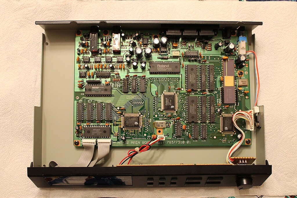
I'm presently converting an MT-100 'revision 1' board to work in a MT-32 revision 0 chassis. There are actually a fair amount of differences and it appears the power connector to drive the LCD display isn't actively supplying power (Roland left out a few things like resistors and diodes).

--> if no one was aware, the revision 1 MT-32s and MT-100s use the same base board, but depending on its configuration it will have different components soldered in.

Wondering if anyone can provide a fairly decent photo of a revision 1 (not 0) motherboard so I can compare if I'm missing anything on the conversion process. I'm also curious what type of voltage regulator it uses as the MT-100 may be using an excessive one to drive the rest of the MT-100.

Reply 1 of 14, by DataPro

User metadata
Rank Member
Rank
Member

1024px-Roland_MT-32_Oldtype_Revision_1_PCB_View.jpg

HP Vectra 562 P166Mhz/256Ko L2 cache/Triton 430FX - 112Mo RAM - 2x 32Go+64Go CF Card - Matrox G2 8Mo - SB AWE64 ISA (PnP) + Roland MT-32 & M-GS64 (SC-88) & JV-1010 - Nec USB 2.0 PCI - Promise Ultra100 TX2 - Hama multicard reader

Reply 2 of 14, by raymangold

User metadata
Rank Member
Rank
Member

That would be the revision 0 (no headphone jack), looking for a motherboard photo of revision 1 with the headphone jack 😉
Surprisingly enough there doesn't seem to be a photo of one on the entire internet.

Reply 4 of 14, by raymangold

User metadata
Rank Member
Rank
Member
vetz wrote:

I'll see what I can do. Both the MT32's I own turned out to be rev 1 when I received them.

Yeah if you could take a decent photo of the mobo that would be great. This would also allow me to publicly outline the process on converting an MT-100 into a revision 0 MT-32 chassis-- as it seems no one has done this before, or at least talked about it? A fair bit of soldering required, but nothing too complex-- it's good to replace all of the aging capacitors in the process anyways.

One curiosity is that the MT-32s (both revisions) actually use BIPOLAR electrolytics, which is very uncommon to see in digital synthesizers... which means people who complain that the MT-32 is noisy don't realize that Roland actually put effort into it.

The remaining guts will be a sad MT-100 chassis swithout its MT-32 board, and a loose rev 0 board missing its connectors (coincidentally it also happens to have been modded with the 'RealWorld' interface and a backup battery). Not sure what to do with either of them as a rev 0 board can't fit in an MT-100 chassis as it lacks the extra power pads.... well theoretically you could modify it to mimic the power pads by modifying the power section but ehhh.... I don't think anyone would want an "MT-10" (a joke at the fact it would be the first MT-100 with a rev 0 board).

Reply 6 of 14, by DataPro

User metadata
Rank Member
Rank
Member

Sorry for the mistake... the photo was labelled as Rev.1. I forgot to check headphones plug...

I can't photograph mine because it's also and rev.0

HP Vectra 562 P166Mhz/256Ko L2 cache/Triton 430FX - 112Mo RAM - 2x 32Go+64Go CF Card - Matrox G2 8Mo - SB AWE64 ISA (PnP) + Roland MT-32 & M-GS64 (SC-88) & JV-1010 - Nec USB 2.0 PCI - Promise Ultra100 TX2 - Hama multicard reader

Reply 7 of 14, by raymangold

User metadata
Rank Member
Rank
Member
Cloudschatze wrote:

While that does have (somewhat) of a photo, it's repeating things from the solder mask that I'm already aware of. I need a photo of a rev 1 board to confirm what the solder mask isn't clear of in certain areas, and also to determine what components are different from the MT-100 and MT-32 boards. Because the schematic just shows everything which is unhelpful.

I'm also curious to see what regulator a revision 1 MT-32 has. If I had a unit myself I would have long since taken a photo for wikipedia.

Reply 8 of 14, by raymangold

User metadata
Rank Member
Rank
Member

10849970_385833744928809_7115093765342886623_n.jpg?oh=64c62fd9d4a5e591f80ae355994530be&oe=54FB0403

Okay I decided to take a photo of (my) board and explain why I need another photo of a rev 1 MT-32 board.

On the right you'll see the voltage regulator is considerably larger and even has its own PCB with a (filter?) capacitor. Because the PCB wouldn't fit flush against the MT-32 chassis I used some wire to bring the PCB away from the VRM. Just above that is the main power section of the board, it uses I believe considerably larger uF values than a non-MT-100 board (to compensate for the extra power draw of the extra junk at the top of the MT-32 board) and there's also a connector CN7 populated used to send power to the top MT-100 circuitry. To the very far left is an extra connector used by the MT-100, and I had to desolder the headphone audio jack so the MT-32 rev 1 board would fit in the rev 0 chassis.

Finally at the bottom is the power connector for the LCD screen. I am not sure if this is the correct orientation because the solder mask indicator is a bit vague, but I believe that it is (which would mean the orientation is inverted from a rev 0 board).

So I'm not sure if that resistor near the LCD power connector needs to be populated, I'm not sure if I can reduce the uF of the power filter caps and I'm also not sure if I can go back to using the regular VRM as used by a rev 0 MT-32. There may also be other variances I'm not aware of-- which as you can see would all be solved by a simple photo which for some reason does not exist on the entire internet.

And I did change a lot of the capacitors and did extensive solder work on that board if anyone was wondering. Like ALL Roland PCBs it is extremely easy to work on.

Reply 9 of 14, by PhilsComputerLab

User metadata
Rank l33t++
Rank
l33t++

Was your MT-32 modified? I just took some images of a MT-32 (New) and they are uploading.

YouTube, Facebook, Website

Reply 10 of 14, by raymangold

User metadata
Rank Member
Rank
Member
philscomputerlab wrote:

Was your MT-32 modified? I just took some images of a MT-32 (New) and they are uploading.

Hey Phil,

That is actually an MT-100 board; prior to my modifications it was missing the majority of the connectors that you now see present. I never bothered to remove the MT-100 specific connectors, so there will be some extra ones as a result.

I purchased an MT-100 and a rev 0 MT-32 to create a discreet rev 1 MT-32-- as at the time there were no rev 1 MT-32s available (of course one did pop up a week later for rather cheap, but since I already bought my parts I opted out).

Since the rev 0 MT-32 I bought ended up having the 'real world interfaces' modification w/ battery, I can write a tutorial to undo those changes if anyone is interested. Because I am also lacking another chassis, I should see about reverse engineering the front LED panel, too.

Reply 12 of 14, by raymangold

User metadata
Rank Member
Rank
Member
philscomputerlab wrote:

Forgot about the images 😊

http://imgur.com/a/Wq6JG

Hope this helps you out...

Awesome thanks Phil!

So for starters:
#1 the old voltage regulator is present in both the Rev 0 / 1 MT-32s. It's just the MT-100 that uses the larger one.
#2 there is indeed a resistor missing, along with two ceramic capacitors and the power section has a few components shuffled around.
#3 the rev 1 boards do have the LCD power connector inverted from the rev 0 boards.
#4 the MT-100 boards are fitted with larger capacitors (which isn't necessary for a stand alone MT-32)

Well, time to get soldering... I'll update here later to see if the conversion is successful (I never tested the board in the MT-100 and have no clue of any reprimands).

Reply 13 of 14, by PhilsComputerLab

User metadata
Rank l33t++
Rank
l33t++

If you need closer images of certain areas just let me know! Happy to help. The unit is really quick to open 😀

I got a MT-100 but it seemed a bit more work to open the unit so I left it.

YouTube, Facebook, Website

Reply 14 of 14, by raymangold

User metadata
Rank Member
Rank
Member

We now have power going to the LCD after reworking the circuitry with Phil's photos (and I switched it to use the smaller voltage regulator):
10696364_386260028219514_1271586384433506093_n.jpg?oh=20119c1e35ff4e81df521575528aa0bf&oe=5541769F

Although as I suspected, it powers on with no splash screen or any indication of life. I'm not even sure how well it will operate without its malignant MT-100 top half-- i.e. if it can still respond to MIDI commands. Why is that? Well if we take a look at the BIOS chip, it's not at all like the one on Phil's MT-32, it's shorter and doesn't have a UV window. Circled here:
10857916_386260058219511_5524418110551091606_n.jpg?oh=0a7e903835be431822322953d9eea1bc&oe=550066EB

So it appears these MT-100 boards were flashed with some 'dumber' firmware. I'm going to open the top half of the MT-100 to see what kind of logic is there. UNFORTUNATELY the rev 0 firmware ROMs are different (A B and C chips), whereas this one isn't labeled with a letter. If I can't find a ROM image I might have to buy a rev 1 MT-32 after all (blah!) I would also have to buy a chip programmer-- something that I've been holding off.

EDIT:

So after gutting out the top MT-100 half (and pulling out that weird floppy drive), it appears there's a BIOS chip on the top as per my hypothesis:
10294493_386271378218379_5947161647843418328_n.jpg?oh=a59359b878260e6cd2ae760402046b92&oe=550F1E0E&__gda__=1425696612_188615daf38b3e24a48eae6b64a13935

I'm going to try soldering it in place of that weird one presently on the MT-32 board... I have a feeling that acts as some sort of redirection chip and not a real BIOS.