First post, by Thermalwrong
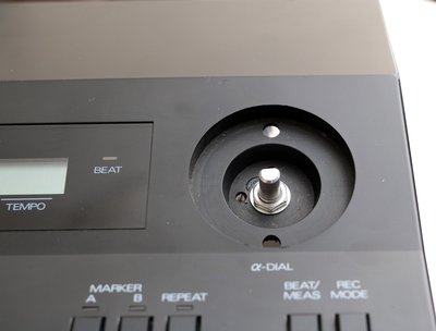
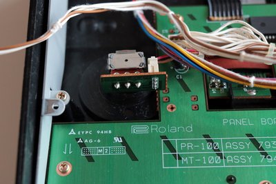
I got a Roland MT100 recently, which is close enough to an MT-32 that I think it's okay to post it here. Sadly, the dial that controls most of the settings was not working correctly and would only make values go down when it was scrolled in either direction.
There's not much information online about the MT100 alpha dial/wheel from what I can tell. But while searching for roland rotary encoders, I found that the dial is the same as a Roland Alpha Juno uses:
http://studiorepair.com/gallery/Roland/JU-2/s … 1506032655.html
This part seems to be completely unavailable, but these two websites worked out which part fits as a replacement:
https://supersynthprojects.com/roland-superjx … er-replacement/
simplified diagram:
http://llamamusic.com/mks50/mks-50_info.html#encoder
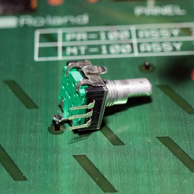
This is the replacement part: https://uk.rs-online.com/web/p/mechanical-rot … coders/7816824/
Not too pricey 😀 The datasheet shows it has Channel A, Channel B and the center pin is the common pin, which afaik it puts a low voltage into.
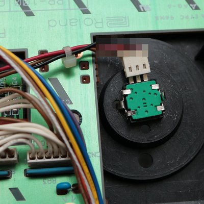
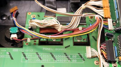
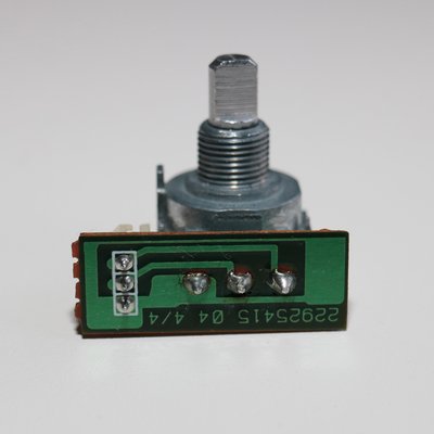
The MT-100's wheel is a little different though, it has a board that it fits to, which has a push on connector:
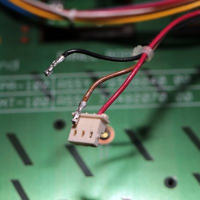
The original connectors layout, on both the plug and where the cable connects to on the mainboard, when interpreted using the details from the replacement Bourns rotary encoder:
Pin 1 - Black Wire - Channel B
Pin 2 - Brown Wire - Channel A
Pin 3 - Red Wire - Common
Remove the pins of the connector using a very small screwdriver / pin pushing down onto the exposes clip parts of the connector to remove the pin from the plug:
The pin sizes of the Roland dial connector match up quite well with the replacement's legs, which can be carefully fitted into the cable. Notice that one of the retention legs on the new rotary encoder is bent around so that's facing up along with the stalk - that's to fit into one of the mounting holes in the MT-100's casing, which stops the rotary encoder from possibly rotating once it's screwed into place: