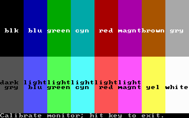
You're confusing two things here - the BIOS mode 6 composite artifact colours (two of which are identical greys, bit patterns 0101 and 1010, as a result of the way that artifact colours are generated), and the "chroma colours" which are the solid colours available in text modes (which have two distinct greys).
By changing the palette register in BIOS mode 6 you can actually get 256 possible colours as combinations of the chroma and artifact colours. At http://www.reenigne.org/misc/artifact_practice_short.png there is a photo of a composite monitor showing all these 256 colours at once - you can see the chroma colours down the right hand side and the artifact colours across the bottom.
To clarify, I am more leaning towards a keycombination to toggle composite/rgb rendering. This combo should work for both modes (4 and 6), but I don't want to drop the current autodetection in mode 6.
A specific monitor type is something that is being considered, but not anytime soon.
To clarify, I am more leaning towards a keycombination to toggle composite/rgb rendering. This combo should work for both modes (4 and 6), but I don't want to drop the current autodetection in mode 6.
A specific monitor type is something that is being considered, but not anytime soon.
So the default rendering would be RGB for Mode 4 and composite for Mode 6 with color burst and the keypress should change it to Mode 4 composite and Mode 6 RGB. That would work just fine.
Another question is which type of encoding should be emulated; "new" CGA (IBM P/N 1501981) or "old" CGA (1501486).
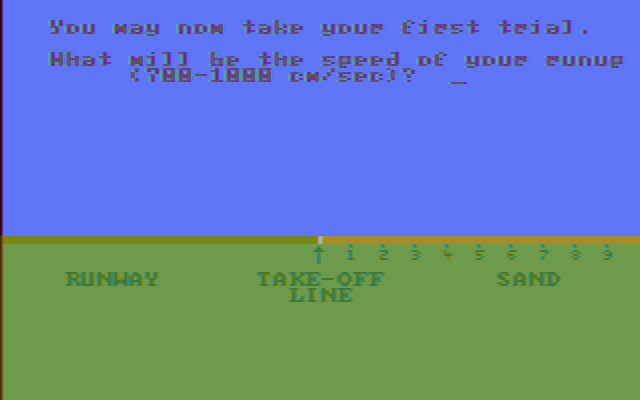
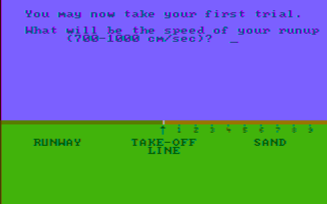
At least one game (MS Decathlon) seems to expect the older model. See the attached images.... as you can tell by the text, it doesn't play very nice with the later cards.
On the other hand, I'm sure we could find an opposite example if we looked hard enough, so I guess this should be user-selectable somehow. Not terribly important at this stage, though.
could a new vs old cga be a reason for why some games need hue changed by 15 degrees?
The hues of both chroma and artifact colours should be the same between old and new CGA - only the brightnesses and saturations should be different. The hues of some of the colours formed by the interaction between chroma and artifact colours might be different, though (but probably not consistently by 15 degrees).
What's an example of a game that needs the hue changed by 15 degrees, and how do you know when it's right? One explanation could be that the game's developer used a composite monitor that was not adjusted correctly.
There's also the Tandy 1000 hue issue which is separate (the artifact colours there are different from the CGA's by about 135 degrees because of a difference in the relative phases of the pixel clock and the chroma signals).
The attached patch is an implementation of the keybind approach with composite auto/on/off logic. As a framework, I think it's fairly complete; but an accurate lowres palette algorithm still needs to be implemented, of course. I've also attached a Win32 build of current source with the patch applied.
To give a more full impression of how it might work some day, I've included a lowres mode hack using NewRisingSun's composite palettes from Wikipedia with some simulated luma leveling. The results are rough around the edges, but (surprisingly) not too bad. Background color and disabled color burst in mode 5 are not handled.
A previous statement of mine warrants a correction:
NTSC assumes a color space vastly different than today's sRGB monitors (see NTSC Wikipedia article). Thus, after producing RGB values using the regular YIQ-to-RGB conversion matrix (as used in DosBox' implementation), these RGB values then need be converted from NTSC-monitor RGB values to sRGB-monitor RGB values (called Color Management in Adobe Photoshop, for example) using the appropriate color correction matrix on non-gamma-corrected values. This holds not just for NTSC emulation on computer emulators but for any television set made after 1960.
The "non-standard" or "wide-angle" YIQ-to-RGB conversion matrices are merely the result of folding both matrices into one, tolerating the error produced from working on gamma-corrected values. Therefore, the so-called "wide-angle demodulation" matrix is actually the correct combined matrix for a particular television set having particular display characteristics, not some random "store-display prettifier".
(In the unlikely event that someone is interested in the technical background and mathematical details of how to produce the correct matrices, the reference is Parker, N.W. (1966): An Analysis of the Necessary Receiver Decoder Corrections for Color Receiver Operation with Non-Standard Primaries. IEEE transactions on broadcast and television receivers, vol. BTR-12, no. 1, pp. 23—32.)
An idealized implementation for DosBox would be to take the RGB values produced from the existing YIQ-to-RGB matrix, convert to linear values (undoing gamma correction, using floating point naturally), apply the set of equations starting with "R709=1.5073*Rntsc" from this page (ignoring the inaccurate information at the top), then converting to gamma-corrected values again. This would be very computationally intensive if done for every single pixel, but since I understand DosBox uses a palettized mode for composite emulation and recalculates color register values only upon register writes, this should be no issue.
VileRancour wrote:
Another question is which type of encoding should be emulated; "new" CGA (IBM P/N 1501981) or "old" CGA (1501486).
I am actually not sure any more which one is the older one. The schematics in IBM's reference manuals differ quite substantially across manual editions. The schematic from August 1981 (page D-29 in reference manual part# 6025008) would more-or-less produce a picture like card part# 1501981, but the resistors are labeled and arranged differently. The schematic from April 1983 (page D-40 in reference manual part# 1502237) resembles card part# 1501486 in board layout. The schematic from 1984 (page 32 in reference manual part# 6361509) resembles card part# 1501981 in board layout.
That doesn't mean that 1501981 is a newer revision though, because a price list from late 1981 lists that very part number for the Color/Graphics Monitor Adapter.
Last edited by NewRisingSun on 2012-04-18, 18:03. Edited 4 times in total.
That hue offset is emulating a particular clone behaviour around an unused bit.
KQ1 booter benefits from it.
Oh yes, I remember that thread now that you mention it. I just tracked it down and 40 Column Text Mode Issues seems to be the relevant page. I thought it was a very strange behavior until I read NewRisingSun's reply (third one down) which makes it all make sense. There's no actual hardware on which modifying bit 5 of port 0x3d9 has an effect on the hue of BIOS mode 6. Here's what happened:
* Somebody made screenshots of KQ1 for MobyGames using 15 degrees of hue shift from what most other composite game screenshots used, possibly because it made it makes the yellows a bit warmer, which makes it slightly more attractive.
* Somebody noticed that the hue for DOSBox for KQ1Booter didn't match the screenshot, and may have assumed that meant that DOSBox was "wrong" (neither is really wrong given the variation in real hardware, but the unshifted hue matches the theoretical NTSC specification).
* Somebody noticed that KQ1Booter sets port 0x3d9 bit 5 (which has no effect on real hardware in this mode) differently from most other other games.
* Somebody thought that it would be a good idea to use this register bit to detect when KQ1Booter is running and set the hue differently in that case to make it look "better" and/or to match the screenshot.
* People got confused and assumed that because an emulator did this, there must have been some real hardware that did the same thing.
Personally I don't really like hacks like that because they complicate things and confuse people just to make the output subjectively more attractive. If you really wanted to have different default hues for different games it would be just as valid (and less confusing) to checksum the code segment and use that to look up the hue adjustment in a table - at least that way it would be clear that it's done that way for the purposes of prettifying rather than accuracy. I won't lose any sleep over it if you want to leave it in though.
NewRisingSun wrote:A previous statement of mine warrants a correction: […] Show full quote
A previous statement of mine warrants a correction:
NTSC assumes a color space vastly different than today's sRGB monitors (see NTSC Wikipedia article). Thus, after producing RGB values using the regular YIQ-to-RGB conversion matrix (as used in DosBox' implementation), these RGB values then need be converted from NTSC-monitor RGB values to sRGB-monitor RGB values (called Color Management in Adobe Photoshop, for example) using the appropriate color correction matrix on non-gamma-corrected values. This holds not just for NTSC emulation on computer emulators but for any television set made after 1960.
The "non-standard" or "wide-angle" YIQ-to-RGB conversion matrices are merely the result of folding both matrices into one, tolerating the error produced from working on gamma-corrected values. Therefore, the so-called "wide-angle demodulation" matrix is actually the correct combined matrix for a particular television set having particular display characteristics, not some random "store-display prettifier".
(In the unlikely event that someone is interested in the technical background and mathematical details of how to produce the correct matrices, the reference is Parker, N.W. (1966): An Analysis of the Necessary Receiver Decoder Corrections for Color Receiver Operation with Non-Standard Primaries. IEEE transactions on broadcast and television receivers, vol. BTR-12, no. 1, pp. 23—32.)
Fascinating - thanks!
NewRisingSun wrote:
An idealized implementation for DosBox would be to take the RGB values produced from the existing YIQ-to-RGB matrix, convert to linear values (undoing gamma correction, using floating point naturally),
The RGB values produced from the existing YIQ-to-RGB matrix aren't gamma corrected, are they? I don't see anything that looks like gamma correction in the existing DOSBox code, and if I gamma correct the output of that I get something which looks much more like the output of the TV connected to the composite output of my CGA card (hence VileRancour's "darker" screenshots earlier in this thread).
If that's the case then using a different YIQ-to-RGB matrix would just be another linear space transformation and no more expensive than the existing code.
NewRisingSun wrote:
VileRancour wrote:
Another question is which type of encoding should be emulated; "new" CGA (IBM P/N 1501981) or "old" CGA (1501486).
I am actually not sure which one is the older one. The schematics in IBM's reference manuals differ quite substantially across manual editions. The schematic from August 1981 (page D-29 in reference manual part# 6025008) would more-or-less produce a picture like card part# 1501981, but the resistors are labeled and arranged differently. The schematic from April 1983 (page D-40 in reference manual part# 1502237) resembles card part# 1501486 in board layout. The schematic from 1984 (page 32 in reference manual part# 6361509) resembles card part# 1501981 in board layout.
That doesn't mean that 1501981 is a newer revision though, because a price list from late 1981 lists that very part number for the Color/Graphics Monitor Adapter.
I definitely think the 1501486 design is earlier because the changes in 1501981 correct a definite problem with the 1501486 (can't distinguish between different colours on a monochrome composite monitor). My best guess is that the schematics in the scan of the 6025008 manual that's available online are actually from a much later manual than 1981.
That's interesting about the price list though. I'd be interested to see that - is it online anywhere? Perhaps the 1501981 was developed very soon after the 1501486 and they were both sold for a while but the schematics in the manuals didn't necessarily keep up with the board versions actually being shipped.
The RGB values produced from the existing YIQ-to-RGB matrix aren't gamma corrected, are they? I don't see anything that looks like gamma correction in the existing DOSBox code, and if I gamma correct the output of that I get something which looks much more like the output of the TV connected to the composite output of my CGA card (hence VileRancour's "darker" screenshots earlier in this thread).
If that's the case then using a different YIQ-to-RGB matrix would just be another linear space transformation and no more expensive than the existing code.
AFAIK, the NTSC-to-sRGB conversion matrix works correctly only with gamma=1, i.e. with a linear relation between coefficients and, basically, the amount of light energy per second per square meter emitted by the screen for a particular primary color. Since most monitors use a gamma value that's quite a bit different from 1, I wouldn't assume that the conversion is nearly correct without undoing then redoing gamma befor/after the conversion.
The RGB values produced from the existing YIQ-to-RGB matrix aren't gamma corrected, are they?
Yes they are, but not in the way you're thinking. Let's replace this with more precise terminology to clear up the confusion:
Computer graphics' RGB signals are assumed to be suitable for a CRT tube having a non-linear voltage-to-light transfer characteristic. In that sense, they are "non-linear" signals. The "gamma-corrected" terminology comes from television: A color television camera measures light with a linear light-to-voltage transfer characteristic (double the light means double the voltage), then applies a transfer characteristic of 0.45 so that the signal produced looks right on a CRT having a non-linear transfer characteristic of 2.2, hence the signal produced is "gamma-corrected".
Computer graphics don't originate from a television camera, but are based on the artist deciding RGB values directly, so no gamma correction is "applied" in the literal sense, however since they are still suitable for a CRT monitor having a non-linear voltage-to-light transfer characteristic, they are still "non-linear" signals, and to call them "gamma-corrected signals" is basically carrying over the lingo from the television into the computer graphics world.
Accurate color conversion can not be done using such non-linear signals. They must (!) first be converted to linear signals. Let R, G, B denote the non-linear signals as normally used in computer graphics and as produced by the YIQ-to-RGB conversion matrix:
Most CRT television sets don't convert to linear RGB, as that is difficult with analogue electronics, but just apply the conversion matrix to the non-linear voltages from the YIQ decoder. You can choose to do that, but the proper matrix will then be certainly not the one on the page I linked!
In fact, because this "lazy man's approach" will inevitably produce color errors, such a "matrix for non-linear signals" is obtained by way of minimizing the errors for two arbitrarily chosen colors. The derivation is mathematically detailed in the N.W. Parker paper I cited. This is actually more involved than doing the simple linearization I made above. 😀
That's interesting about the price list though. I'd be interested to see that - is it online anywhere?
Actually I misremembered --- the price list is here, but it lists a completely different part number: 1504910. This picture linked from an ebay auction shows the board layout for the composite video section. From the resistor labeling, it resembles the 6361509 layout (resistor R20 present). Of course, it could just be that the part number in that picture is misidentified!
Last edited by NewRisingSun on 2012-04-18, 20:50. Edited 1 time in total.
@NewRisingSun: interesting -- thanks for weighing in on this. "Old"/"new" are just a convenience to differentiate the two implementations, though it would be intriguing to find out which one actually came first. Emulation-wise, both should be useful, as far as there are games that work best with a specific CGA revision.
reenigne wrote:
* Somebody noticed that KQ1Booter sets port 0x3d9 bit 5 (which has no effect on real hardware in this mode) differently from most other other games.
* Somebody thought that it would be a good idea to use this register bit to detect when KQ1Booter is running and set the hue differently in that case to make it look "better" and/or to match the screenshot.
...and now I know why fiddling with that bit in gwbasic was causing DOSBox to subtly alter the colors - that one had me puzzled, so thanks for unearthing the reason. :)
ripsaw8080 wrote:
The attached patch is an implementation of the keybind approach with composite auto/on/off logic. As a framework, I think it's fairly complete; but an accurate lowres palette algorithm still needs to be implemented, of course. I've also attached a Win32 build of current source with the patch applied.
To give a more full impression of how it might work some day, I've included a lowres mode hack using NewRisingSun's composite palettes from Wikipedia with some simulated luma leveling. The results are rough around the edges, but (surprisingly) not too bad. Background color and disabled color burst in mode 5 are not handled.
The toggle key approach seems to work very nicely. Not that it matters very much, but I don't know if three states are really necessary (on/off/auto) - it would also be possible to always let DOSBox do its auto-detection, then the key event would just act as a "virtual switchbox" to toggle between RGB and composite output.
As for the hard part (refactoring the proposed code to work with DOSBox's palette precalculation), here's what I was thinking: derive the 16 pixel patterns corresponding to each nybble for the current mode/color register, and feed them to reenigne's code (upsampled as necessary - the algorithm samples 1280 "sub-pixels" per scanline). For each nybble, take the result after 8 iterations (a full color-burst cycle), then use these values to populate the palette in the same way as the current implementation.
That's what I want to try myself, though I'll probably need to familiarize myself with dosbox internals a bit more. It wouldn't give the most precise results, but would probably work best within the limitations of using a palette; might be possible to fine-tune it later.
dosbox its algorithm, while called a palette implementation is not that different from you would expect though; it (pre)calculates 80 colours and stores them in the upper bits of the current vga palete.
Most CRT television sets don't convert to linear RGB, as that is difficult with analogue electronics, but just apply the conversion matrix to the non-linear voltages from the YIQ decoder.
Ah, here's where the confusion lies then - my understanding is that the voltages (composite, Y, I, Q and the R, G and B that come from the YIQ->RGB matrix) were all linear. For example, if you oscillate between 0V and 1V at a 50% duty cycle and then low-pass filter the result you'll get 0.5V which is exactly what you'd expect from a linear measure. Whereas if I draw a repeating pattern of black (value 0) pixels and white (value 255) pixels on an sRGB computer screen, the resulting average shade of grey will not be the same as the value 128 grey. In a TV, the "gamma correction" (conversion from linear voltage to non-linear intensity) is done by the cathode ray tube itself, no complex analogue electronics required.
If that's not the case, can you go into more detail about what the non-linearities in the YIQ signals are and what they mean? Is this the same thing as the effective 1.1-1.2 exponent power function mentioned in section 10 of http://www.poynton.com/notes/colour_and_gamma/GammaFAQ.html? That's a much smaller effect than the usual 2.2 gamma used to convert from linear to sRGB though.
NewRisingSun wrote:
the price list is here, but it lists a completely different part number: 1504910.
Very interesting - that's the one that I haven't been able to find an image for. Though I have seen that same part number in 1986 price lists. Which makes me wonder if 1504910 refers to "a CGA card in general" and 1501486 and 1501981 refer to specific circuits. IBM probably would have needed a way to refer to "whatever version of CGA card is currently available" (for price lists and ordering) independently of the specific part numbers (which would have been useful for servicing). So you'd order a 1504910 and you'd receive either a 1501486 or a 1501981 depending on what year it is. I bet that's what it means.
NewRisingSun wrote:
This picture linked from an ebay auction shows the board layout for the composite video section. From the resistor labeling, it resembles the 6361509 layout (resistor R20 present). Of course, it could just be that the part number in that picture is misidentified!
Yeah, I bet that is actually a 1501981 card. It's not exactly the same as the one at http://www.yjfy.com/museum/video/Video_8-bit_ISA.htm (C7 has moved) but I think it's probably a different board revision of the same schematic. It seems to have too many resistors to be the card documented in IBM_5150_Technical_Reference_6025005_AUG81.pdf (the 6025008 manual).
NewRisingSun wrote:
It is interesting to note that:
- the 6025008 manual doesn't list the resistor values, while all others do;
- the resistor numbers go no higher than R10 for 6025008 (said to be from1981), up to R17 for 1502237 (said to be from 1983) and up to R20 for 6361509 (said to be from 1984).
Very interesting, and does lend weight to the theory that the 6025008 schematic is the earlier one (though the circuit itself seems to be in between the 1502237 circuit and the 6361509 circuit).
Not that it matters very much, but I don't know if three states are really necessary (on/off/auto) - it would also be possible to always let DOSBox do its auto-detection, then the key event would just act as a "virtual switchbox" to toggle between RGB and composite output.
That would be annoying in games that switch between text mode and mode 4, like Ultima 2 for example, because you'd have to keep toggling composite back on whenever mode 4 was set again. What made sense to me was 3 states that are set independent of what mode happens to be active at the time and that cover all the combinations:
Auto is needed for mode 6 auto-detection.
On is needed to switch to composite in mode 4.
Off is needed to switch to RGB in mode 6 when the color burst bit is set.
Off could easily be omitted because it's not terribly useful. I remember a thread started by someone who actually wanted the vertical line patterns because it's what they remember, but probably an exceptional case. 😉
Last edited by ripsaw8080 on 2012-04-18, 22:01. Edited 1 time in total.


