VOGONS

Common searches


Reply 200 of 758, by reenigne

User metadata
Rank Oldbie
Rank
Oldbie
VileRancour wrote:

As for the hard part (refactoring the proposed code to work with DOSBox's palette precalculation), here's what I was thinking: derive the 16 pixel patterns corresponding to each nybble for the current mode/color register, and feed them to reenigne's code (upsampled as necessary - the algorithm samples 1280 "sub-pixels" per scanline).

Just as an aside, I no longer think that 1280 samples is the best way to go - the next version of my algorithm will go back to using 640. I was under the mistaken impression that the yellow/red/blue/cyan chroma signals were exactly half a pixel out of phase with the green/magneta ones and the pixel grid but slight logic delays in the CGA card means that's not true. 640 samples is really enough, but makes ANDing the chroma signals with the pixel signals rather more difficult (which it will be anyway because of the logic delays).

VileRancour wrote:

For each nybble, take the result after 8 iterations (a full color-burst cycle), then use these values to populate the palette in the same way as the current implementation.

Hmm... that'll just give you 16 possible colours for each mode though won't it? Meaning that the areas of solid colour will be correct but the "fringes" where one colour blends into an adjacent one will work worse than it currently does. Getting the fringing right seems like it would be just about impossible with an 8-bit palette though. Maybe an RGB colour cube palette would be the best way?

Reply 201 of 758, by NewRisingSun

User metadata
Rank Oldbie
Rank
Oldbie

In a TV, the "gamma correction" (conversion from linear voltage to non-linear intensity)

No, the non-linear voltage-to-light transfer characteristic is usually not described as gamma correction, that's just called "the non-linearity in the television display tube". Gamma correction happens in the television camera, not the viewing CRT. You can understand it as a way of distorting an electrical signal representing light so as to accomodate the viewing device's peculiarities.

If that's not the case, can you go into more detail about what the non-linearities in the YIQ signals are and what they mean?

The "non-linearity" merely refers to what the electrical (or digital) RGB signals actually represent. A linear signal directly represents light, because double the voltage means double the light, whereas a "non-linear" signal doesn't directly represent light, because it's "distorted", if you will, in a particular way to accomodate the viewing device. That's basically it. And because color manipulations work on light and not on some distorted electrical representation of it, you need to work with linear, that is, light-representing signals. 😀
And a YIQ signal is just a funny (i.e. bandwidth-saving and black-and-white TV compatible) way of transmitting an RGB signal.

For example, if you oscillate between 0V and 1V at a 50% duty cycle and then low-pass filter the result you'll get 0.5V which is exactly what you'd expect from a linear measure. Whereas if I draw a repeating pattern of black (value 0) pixels and white (value 255) pixels on an sRGB computer screen, the resulting average shade of grey will not be the same as the value 128 grey.

True. As you know, that's how monitor calibration program measure a monitor's gamma.

Is this the same thing as the effective 1.1-1.2 exponent power function mentioned in section 10 of http://www.poynton.com/notes/colour_and...maFAQ.html? That's a much smaller effect than the usual 2.2 gamma used to convert from linear to sRGB though.

No, that refers to the camera gamma-correcting with value 1/2.2, even though a real CRT (supposedly) has a gamma of 2.5, effectively under-correcting the signal by a factor of 2.5/2.2=1.13636.. (which is where the 1.1/1.2 value comes from), causing it to be reproduced darker on the CRT than what the camera originally saw. I consider that information rather dubious and, in any case, irrelevant to the issue here.

IBM probably would have needed a way to refer to "whatever version of CGA card is currently available" (for price lists and ordering) independently of the specific part numbers (which would have been useful for servicing).

I almost agree: 1504910 probably refers to the box containing a CGA card (having its own part number, either 1804472, 1501486 or 1501981) and installation instructions (again having their own part number, which I don't know). That would explain why the auction picture I linked to earlier used that part number, because that auction sold a boxed CGA with instructions. To verify this, one would need to have a boxed CGA and look what number is printed on the box.

Very interesting, and does lend weight to the theory that the 6025008 schematic is the earlier one (though the circuit itself seems to be in between the 1502237 circuit and the 6361509 circuit).

I could imagine that the 6025008 was the earliest circuit from a concept stage (hence without having decided on resistor values), but actual production used the simplified 1502237 design for cost --- assuming that no person would buy a color graphics card and then use it with a monochrome monitor! ---, only to revert to the more complex design in 6361509 when it was found that the simplification wasn't such a good idea after all.

On the other hand, the relevant patent 4,442,428 clearly shows the 1502237 circuit, so I don't know what to make of that.

Reply 202 of 758, by reenigne

User metadata
Rank Oldbie
Rank
Oldbie
NewRisingSun wrote:

The "non-linearity" merely refers to what the electrical (or digital) RGB signals actually represent. A linear signal directly represents light, because double the voltage means double the light, whereas a "non-linear" signal doesn't directly represent light, because it's "distorted", if you will, in a particular way to accomodate the viewing device. That's basically it. And because color manipulations work on light and not on some distorted electrical representation of it, you need to work with linear, that is, light-representing signals.

Okay, having read through that and your other posts today a few times and thinking about it for a bit, you've convinced me - the voltages inside the composite monitor (composite, Y, I, Q and the output of the YIQ->RGB matrix) don't have a linear relationship with light intensity, but do have (approximately) a linear relationship with sRGB values. Hence the current DOSBox composite decoder is correct in that it does not apply a gamma correction curve to the NTSC decoder output before displaying it (the user's output device does that). Sorry about that, VileRancour!

However, that means that the NTSC decoding itself that we're doing is not mathematically correct because we're treating the values as linear (doing things like using a linear YIQ->RGB transformation matrix, convolving with a linear filter kernel for band-limiting the Y, I and Q signals). But real composite monitors and TVs make the same approximations. So we aren't making a NTSC decoder which reconstructs an original signal as accurately as possible, we're making an NTSC decoder which gives output as similar as possible to a real composite monitor, which is what we want.

Now I understand your comment from 9:04am much better. I'm interested to see what difference it makes doing the conversion from NTSC RGB to 709 RGB in linear vs gamma corrected colour space - the conversion matrix is not enormously far from the identity matrix so the difference might not be very noticable. I'll do some experiments.

I'm still puzzled as to why doing an extra gamma correction seems to produce results much closer to what I see on my TV connected to my CGA card, but perhaps that effect will disappear when I do the comparison under more controlled conditions and adjust the brightness and contrast properly.

I also looked at what some other software NTSC emulators do. xscreensaver's analogtv effect uses an additional gamma of 1.25 (2.5/2.0?) and Blargg's NTSC library has an adjustable gamma control (that goes between 0.5 and 1.5 I think). So a small gamma correction to account for the difference between sRGB and the CRT's voltage/current curve may be appropriate.

NewRisingSun wrote:

I could imagine that the 6025008 was the earliest circuit from a concept stage (hence without having decided on resistor values), but actual production used the simplified 1502237 design for cost --- assuming that no person would buy a color graphics card and then use it with a monochrome monitor! ---, only to revert to the more complex design in 6361509 when it was found that the simplification wasn't such a good idea after all.

That seems unlikely to me - if they hadn't expected people to use the CGA card in monochrome mode why bother to include the +BW register bit (port 0x3d8 bit 2) at all? There were probably quite a few monochrome composite monitors in the wild in 1981, and these wouldn't have been compatible with MDA cards so CGA would have been IBM's solution for them.

Also the 1502237 schematic is not significantly cheaper than the 6025008 one - all the active parts were the same, the only difference is 2 extra resistors.

Here's another possibility: IBM made the 1501486 version first but started work on the fixed version even before the PC shipped. The 6025008 manual accidentally used the (incomplete) updated schematic instead of the one that matched the hardware that they had been building. When the XT shipped they still had a large stock of the 1501486 boards and/or still hadn't finished the 1501981 design so used the (correct) 1501486 schematic in the 1502237 manual.

Reply 203 of 758, by NewRisingSun

User metadata
Rank Oldbie
Rank
Oldbie

doing things like using a linear YIQ->RGB transformation matrix, convolving with a linear filter kernel for band-limiting the Y, I and Q signals

No, that's entirely correct, because YIQ to RGB transformation as well as the band-limiting is even in theory meant to apply to electrical signals, not to light. Unlike color correction, which in theory is meant to apply to light, not electrical signals.

I'm interested to see what difference it makes doing the conversion from NTSC RGB to 709 RGB in linear vs gamma corrected colour space - the conversion matrix is not enormously far from the identity matrix so the difference might not be very noticable.

I'll post examples later.

I'm still puzzled as to why doing an extra gamma correction seems to produce results much closer to what I see on my TV connected to my CGA card

Is it brighter or darker on your TV? Remember that American NTSC uses a black level of 7.5% ("setup"), so you need to do this to your RGB values coming from the YIQ-to-RGB matrix as well:

R = (R - 0.075) / (1-0.075)
G = (G - 0.075) / (1-0.075)
B = (B - 0.075) / (1-0.075)

That black level business is found in all NTSC standards documents, whereas that dubious 2.5/2.2 gamma adjustment business violates the standards, since NTSC and sRGB are supposed to use similar gammas.

And another thing that no one has taken note of so far: real television sets usually do some form of automatic gain control (AGC) on the signal, to compensate for weak signals when receiving via antenna. This is a major source of variation between TV sets when dealing with signals like the CGA's that output somewhat non-standard video levels, because they tend to confuse the AGC circuits.

That seems unlikely to me - if they hadn't expected people to use the CGA card in monochrome mode why bother to include the +BW register bit (port 0x3d8 bit 2) at all?

I've always thought that the BW bit was for people with a color composite monitor who wanted a sharper (non-artifacted picture), not for monochrome monitors.

Reply 204 of 758, by NewRisingSun

User metadata
Rank Oldbie
Rank
Oldbie

Earlier I promised to upload example images demonstrating how properly done color correction from NTSC to sRGB differs from approximately done, that is, applying a correction matrix on non-linear signals. The matrix for the proper correction of linear signals is the one cited earlier:

	      Rs	      Gs      	Bs
Rt= 1.5073 -0.3725 -0.0832
Gt= -0.0275 0.9350 0.0670
Bt= -0.0272 -0.0401 1.1677

Whereas the one for the nonlinear signals, assuming a gamma of 1/0.45 and minimizing color errors for CIE x/y: 0.444/0.399 and 0.309/0.494:

	     Rs	      Gs	      Bs
Rt= 1.5164 -0.4945 -0.0219
Rt= -0.0372 0.9571 0.0802
Rt= -0.0192 -0.0309 1.0500

This corresponds to a NTSC decoder matrix in polar coordinate form of:
R-Y: gain=2.016 angle=81.5°
G-Y: gain=0.668 angle=244.8°
B-Y: gain=2.276 angle=-0.2°

First, a set of "real-life" images from a television camera. First picture is the original uncorrected picture, which doesn't necessarily look ugly, but the faces are somewhat pale. Second is the exact correction from linear signals. Third is the approximation when using non-linear signals. As you can see, both correction methods yield almost identical results in most areas except the very saturated reds, which become too bright in the approximation.

Attachments

  • approximated.png
    Filename
    approximated.png
    File size
    261.95 KiB
    Views
    1631 views
    File comment
    approximate correction using non-linear signals
    File license
    Fair use/fair dealing exception
  • exact.png
    Filename
    exact.png
    File size
    273.6 KiB
    Views
    1630 views
    File comment
    exact correction using linear signals
    File license
    Fair use/fair dealing exception
  • original.png
    Filename
    original.png
    File size
    258.75 KiB
    Views
    1630 views
    File comment
    uncorrected image
    File license
    Fair use/fair dealing exception
Last edited by NewRisingSun on 2012-04-20, 21:46. Edited 2 times in total.

Reply 205 of 758, by NewRisingSun

User metadata
Rank Oldbie
Rank
Oldbie

Second, a set of images from a video game.

Attachments

  • approximated.png
    Filename
    approximated.png
    File size
    70.66 KiB
    Views
    1607 views
    File comment
    approximate correction
    File license
    Fair use/fair dealing exception
  • exact.png
    Filename
    exact.png
    File size
    69.04 KiB
    Views
    1607 views
    File comment
    exact correction
    File license
    Fair use/fair dealing exception
  • original.png
    Filename
    original.png
    File size
    70.22 KiB
    Views
    1607 views
    File comment
    uncorrected image
    File license
    Fair use/fair dealing exception

Reply 206 of 758, by reenigne

User metadata
Rank Oldbie
Rank
Oldbie
NewRisingSun wrote:

No, that's entirely correct, because YIQ to RGB transformation as well as the band-limiting is even in theory meant to apply to electrical signals, not to light.

I'm not convinced about that - it's a linear transformation of voltage but ideally it would be linear transformation of light. Consider a signal that oscillates between 0V and 1V at 7.16MHz with a 50% duty cycle. If that is displayed on a monochrome composite monitor it'll look like a 50% intensity grey. But if we put that signal through the decoder we're currently using in DOSBox (or, presumably, in a colour composite monitor) we'll get a 0.5V signal after the band-limiting, which will correspond to a grey much darker than 50%.

Conceivably signals from a TV camera can be constructed with this in mind, but it seems like any given signal is either going to be too dark on a colour monitor or too light on a monochrome monitor at the boundaries between light and dark, as long as linear filtering is done with voltages.

NewRisingSun wrote:

Is it brighter or darker on your TV?

My TV is much darker than the current DOSBox output, which is one reason why I thought the extra gamma correction was necessary.

NewRisingSun wrote:

Remember that American NTSC uses a black level of 7.5% ("setup")

NewRisingSun wrote:

And another thing that no one has taken note of so far: real television sets usually do some form of automatic gain control (AGC) on the signal, to compensate for weak signals when receiving via antenna. This is a major source of variation between TV sets when dealing with signals like the CGA's that output somewhat non-standard video levels, because they tend to confuse the AGC circuits.

It should be possible to compensate for gain and setup by adjusting the brightness and contrast properly. The CGA card doesn't generate a blank level that differs properly from the black level so that's going to cause some brightness and/or contrast variation between monitors in any case.

NewRisingSun wrote:

I've always thought that the BW bit was for people with a color composite monitor who wanted a sharper (non-artifacted picture), not for monochrome monitors.

It has the same sharpness-improving effect on both colour and monochrome composite monitors. The artifacts will just show up differently - as colour fringes on colour monitors and vertical lines on monochrome monitors (see http://www.vintage-computer.com/vcforum/showt … 9501#post219501 for an example of the problems that can cause).

NewRisingSun wrote:

First picture is the original uncorrected picture, which doesn't necessarily look ugly, but the faces are somewhat pale. Second is the exact correction from linear signals. Third is the approximation when using non-linear signals. As you can see, both correction methods yield almost identical results in most areas except the very saturated reds, which become too bright in the approximation.

Thanks! That looks about how I expected.

Reply 207 of 758, by NewRisingSun

User metadata
Rank Oldbie
Rank
Oldbie

we'll get a 0.5V signal after the band-limiting, which will correspond to a grey much darker than 50%.

As it should. If your purpose of performing the band-limiting is to replicate the blur on a monochrome monitor, then you would be right, and you would have to linearize the signals before applying a linear transformation. But that's not the purpose within the NTSC system --- all transformations performed with the decoder are only designed to recover the original, gamma-correct signal from the television camera. Since the color television camera uses linear transformations to encode the YIQ and then the composite signal, the decoder must use the exact reverse inverse transformations as well, not something else. 😀

should be possible to compensate for gain and setup by adjusting the brightness and contrast properly. The CGA card doesn't generate a blank level that differs properly from the black level so that's going to cause some brightness and/or contrast variation between monitors in any case.

My point was that what some people try to accomplish with the 1.2 gamma adjustment should properly be done by removing the 7.5% setup instead.

he CGA card doesn't generate a blank level that differs properly from the black level

Are you sure? I thought that's what the -BLANK signal in the 1501486 implementation does.

Last edited by NewRisingSun on 2012-04-19, 17:27. Edited 1 time in total.

Reply 208 of 758, by VileR

User metadata
Rank l33t
Rank
l33t
ripsaw8080 wrote:

That would be annoying in games that switch between text mode and mode 4, like Ultima 2 for example, because you'd have to keep toggling composite back on whenever mode 4 was set again.

True, hadn't thought of a situation like that... on/off/auto does make better sense in such a scenario.

ripsaw8080 wrote:

Off could easily be omitted because it's not terribly useful. I remember a thread started by someone who actually wanted the vertical line patterns because it's what they remember, but probably an exceptional case. ;)

Better keep the "off" state I think, if only for completeness' sake / testing purposes. And if someone really wants an ocular migraine, who's to say they shouldn't have one? ;)

reenigne wrote:

Hmm... that'll just give you 16 possible colours for each mode though won't it? Meaning that the areas of solid colour will be correct but the "fringes" where one colour blends into an adjacent one will work worse than it currently does. Getting the fringing right seems like it would be just about impossible with an 8-bit palette though. Maybe an RGB colour cube palette would be the best way?

As Qbix noted, the precalculation produces 80 colors (16 hues * 5 luminance levels for each); the line-drawing handler then determines the palette index for each pixel by doing some averaging over adjacent pixels. If you go back to the Tapper screenshot comparison on page 8, you can see the effect: most areas with colored fringes look acceptable, even though a few scattered errors are visible (for example, the character "1" on the bottom left gets a greyscale transition instead of color blending). So it isn't precise, but for a palette-based approach it seems to work surprisingly well.

If we use your code to calculate the 16 hues, but apply the same Y-leveling that DOSBox currently does to get the 80 colors, I don't think the results should look any worse. Ripsaw's patch on the previous page seems to produce "blockier" fringing - but I *think* that's just because the 16 initial colors are hard-coded with different luminance levels to begin with, so the subsequent leveling and averaging doesn't work as well as it should. Proper calculation should fix that; I'll definitely try it as soon as I find the time.

As for doing color correction the right way - for now I can only take notes from you and NewRisingSun. If there's a consensus on how to apply the proper corrections to your current code, I'll add that in too.

[ WEB ] - [ BLOG ] - [ TUBE ] - [ CODE ]

Reply 209 of 758, by NewRisingSun

User metadata
Rank Oldbie
Rank
Oldbie

As for doing color correction the right way - for now I can only take notes from you and NewRisingSun. If there's a consensus on how to apply the proper corrections to your current code, I'll add that in too.

There will be no consensus until we have decided what we actually want to depict: a theoretically perfect NTSC display? Any particular monitor type? As little processing as possible?

The theoretically perfect NTSC display involves linearizing the RGB signals, then appling the NTSC-to-709 correction matrix, as explained above.

Replicating any particular monitor type involves knowing the NTSC decoding matrix of that particular monitor as well as its phosphor and white point chromaticities. One would decode the YIQ signal exactly as that particular monitor would, then construct a matrix converting RGB values as they look on that monitor to sRGB. This is the most complicated method, but (potentially) the most rewarding.

As little processing as possible means shutting up about color correction completely and keeping the current algorithm, with the 320x200 extension of course.

Reply 210 of 758, by reenigne

User metadata
Rank Oldbie
Rank
Oldbie
NewRisingSun wrote:

As it should. If your purpose of performing the band-limiting is to replicate the blur on a monochrome monitor, then you would be right, and you would have to linearize the signals before applying a linear transformation.

But when the NTSC standard was first developed, that was exactly the idea - the same signal was supposed to be compatible with both monochrome and colour TVs. On a monochrome TV the 3.57MHz chroma patterns would be averaged out by the eye (i.e. in light space) but on a colour TV it would be averaged out by the Y/C separator circuit (i.e. in voltage space). They're supposed to be the same brightness but because one is a gamma-corrected average and the other isn't, they won't be.

NewRisingSun wrote:

But that's not the purpose within the NTSC system --- all transformations performed with the decoder are only designed to recover the original, gamma-correct signal from the television camera. Since the color television camera uses linear transformations to encode the YIQ and then the composite signal, the decoder must use the exact reverse inverse transformations as well, not something else. 😀

Agreed - I think my issue is with the NTSC standard having some theoretical problems, but in practice we just do the linear filtering on voltages and it comes out looking good enough. We definitely want DOSBox to do what real monitors do in this respect anyway, so doing the filtering on voltages is what we want to continue to do, as I said before.

NewRisingSun wrote:

My point was that what some people try to accomplish with the 1.2 gamma adjustment should properly be done by removing the 7.5% setup instead.

That's more than possible.

NewRisingSun wrote:

Are you sure? I thought that's what the -BLANK signal in the 1501486 implementation does.

I had it my head that the effect of -BLANK was much smaller than what NTSC specifies but now that I re-check my notes I see it's the other way around - the difference between black and blank is actually too large.

The NTSC standard voltages are: -0.286V for sync, 0V for blank, 0.054V for black, 0.714V for white and 0.935V for peak. The voltages produced from the CGA (as calculated using Falstad's circuit simulator) are: 0V for sync, 0.292V for blank, 0.416V for black, 0.709V for dark grey, 1.16V for light grey and 1.46V for white. Automatically adjusting the gain and level so that the sync and blank levels are correct (which is what I assume real monitors and TVs do) gives 0.121V for black, 0.408V for dark grey, 0.850 for light grey and 1.15V for white. Black is significantly higher than NTSC standard, so I'd expect it to show up as lighter than black.

That's not what happens on my TV though: with the default brightness and contrast settings, black is black, so maybe it's going the gain control another way, or maybe the default settings are just too dark.

Curiously (I just noticed) colour 8 (dark grey) is much darker (almost indistinguishable from black) when the colour burst is enabled and a much brighter and more sensible level when it's disabled. I guess that's because it's doing gain control based on the average level over the entire blank period, which is higher than it should be because of the DC offset of the color burst. This was fixed in the 1501981 by pulling the -SYNC signal low during the color burst as well as during the horizontal sync pulse and by reducing the chroma signal amplitude.

The -BLANK signal is missing completely in the 1501981 schematic, so that card generates the same voltage for black and blank.

Reply 211 of 758, by NewRisingSun

User metadata
Rank Oldbie
Rank
Oldbie

That's not what happens on my TV though

In any case, the CGA does not generate proper video levels, and having gone back and forth between several ways of dealing with this, I think for emulation purposes, the best way is to just normalize everything so that black really is at 0/0/0 and white is at 1/1/1.

The only question remaining is what to do with the chroma amplitude. The color burst is supposed to be 40 IRE units peak-to-peak. Smaller amplitudes mean that the demodulated color signal is supposed to be amplified, larger amplitudes mean it should be attenuated, before being converted to RGB. In the old CGA revision, the actual peak-to-peak amplitude of the color burst will be larger than 40 IRE units, on the newer, it will be smaller (according to my calculations, it should be 72 IRE units on the old and 0.29 IRE units on the new CGA). Doing the amplification/attenuation of the chroma signal in the manner described would result in direct colors having the same saturation on both revisions, but artifact colors being desaturated on the old and oversaturated on the new revision.

Reply 212 of 758, by reenigne

User metadata
Rank Oldbie
Rank
Oldbie
VileRancour wrote:

As Qbix noted, the precalculation produces 80 colors (16 hues * 5 luminance levels for each); the line-drawing handler then determines the palette index for each pixel by doing some averaging over adjacent pixels.

Having thought about this some more - I think there's a slight variation on this algorithm which will be even faster and give results identical to cga2ntsc.cpp.

If we're doing our band-limiting by just averaging over 4 consecutive pixels (as the current DOSBox implementation does, I think) and we limit ourselves to graphics modes we can just enumerate all the colour possibilities directly in the palette. There are only 64 of them because they depend on only 6 bits of information - 2 bits to determine where the pixel is in the cycle and 4 to index the colours of (2 in low-res) pixels. So then our drawing loop can look something like this:

    for(Bitu x = 0; x < 640; x++)
temp[x+2] = ((temp[x+1] << 1) & 0x0e) | (( reader[(x>>3)] >> (7-(x&7)) )&1);
for (Bitu x=0;x<vga.draw.blocks;x++) {
*draw++ = 0x8090a0b0 | temp[i] | (temp[i+1] << 8) | (temp[i+2] << 16) | (temp[i+3] << 24);
i += 4;
*draw++ = 0x8090a0b0 | temp[i] | (temp[i+1] << 8) | (temp[i+2] << 16) | (temp[i+3] << 24);
i += 4;
}

That won't work for text mode (because a pixel's colour depends on as many as 34 bits of information instead of 6) but I'm not sure how much interest there is emulating composite artifacts in text modes in DOSBox.

In another NTSC decoding program I wrote (http://www.reenigne.org/blog/ntsc-hacking/) I used a 7-sample kernel (1, 4, 7, 8, 7, 4, 1) instead of a 4-sample one (1, 1, 1, 1) which I think gives nicer fringes, but it's not such a good fit for DOSBox because you'd need 10 bits of palette instead of 6. I was actually under the mistaken impression that cga2ntsc.cpp and composite_test.cpp used the 7-element kernel already but I misremembered.

VileRancour wrote:

As for doing color correction the right way - for now I can only take notes from you and NewRisingSun. If there's a consensus on how to apply the proper corrections to your current code, I'll add that in too.

Thinking about it, I'm in favour of using the theoretical ideal NTSC-to-709 matrix since (in combination with the palette method) it's not too slow. I think that was NewRisingSun's preference too. If we wanted to switch away from the palette method so that we could do text mode composite correctly or use a longer filter kernel, then I'd say use the combined YIQ->709 matrix for speed since the difference is quite subtle.

Reply 213 of 758, by reenigne

User metadata
Rank Oldbie
Rank
Oldbie
NewRisingSun wrote:

In any case, the CGA does not generate proper video levels, and having gone back and forth between several ways of dealing with this, I think for emulation purposes, the best way is to just normalize everything so that black really is at 0/0/0 and white is at 1/1/1.

Agreed. I still want to figure out how to set the brightness and contrast of my TV correctly, though, because I want to try to better calibrate some of the other parameters of my algorithm.

NewRisingSun wrote:

The only question remaining is what to do with the chroma amplitude. The color burst is supposed to be 40 IRE units peak-to-peak. Smaller amplitudes mean that the demodulated color signal is supposed to be amplified, larger amplitudes mean it should be attenuated, before being converted to RGB. In the old CGA revision, the actual peak-to-peak amplitude of the color burst will be larger than 40 IRE units, on the newer, it will be smaller (according to my calculations, it should be 72 IRE units on the old and 0.29 IRE units on the new CGA). Doing the amplification/attenuation of the chroma signal in the manner described would result in direct colors having the same saturation on both revisions, but artifact colors being desaturated on the old and oversaturated on the new revision.

I think you meant 29 IRE on the new CGA. That's interesting that the saturation is supposed to depend on the color burst amplitude - I hadn't heard that before. My TV doesn't seem to do that - changing the color burst amplitude has no effect unless it gets too small, at which point the colour killer circuit kicks in and I just a get a monochrome picture.

Bear in mind that the CGA's color burst signal is a square wave so its amplitude relative to the standard is going to be different depending on whether you measure peak-to-peak or RMS.

Reply 214 of 758, by Qbix

User metadata
Rank DOSBox Author
Rank
DOSBox Author

you can use 128 entries if you want. Only the first bit is in the current method required to be set to 1. (so you have 7 bits available)
the draw routine probably can be made a bit more efficient, but please start from the SVN source as that has some bank fixes.

Water flows down the stream
How to ask questions the smart way!

Reply 215 of 758, by NewRisingSun

User metadata
Rank Oldbie
Rank
Oldbie

That's interesting that the saturation is supposed to depend on the color burst amplitude - I hadn't heard that before.

The standards documents are written in beautifully inconvenient language. I'm quoting from SMPTE-170M: "A gated and filtered signal derived from subcarrier, called the burst, shall be added in the horizontal blanking interval of each line, excluding the nine-line vertical sync interval, as a synchronizing signal and amplitude reference for the chrominance signals. The burst signal shall be inverted in phase from the reference subcarrier." The key phrase here is "amplitude reference for the chrominance signals." 😀

Reply 216 of 758, by reenigne

User metadata
Rank Oldbie
Rank
Oldbie
NewRisingSun wrote:

A gated and filtered signal derived from subcarrier, called the burst, shall be added in the horizontal blanking interval of each line, excluding the nine-line vertical sync interval, as a synchronizing signal and amplitude reference for the chrominance signals.

Now you've got me wondering if I was mistaken about the burst amplitude having no effect - I've only played with decreasing the amplitude, not increasing it and if the saturation was at its maximum value then that would account for me not seeing an effect. I have some parts here to build a circuit that can increase the burst amplitude independently of the active video signals so I'll do some experiments.

Reply 217 of 758, by NewRisingSun

User metadata
Rank Oldbie
Rank
Oldbie

Thinking about it, I'm in favour of using the theoretical ideal NTSC-to-709 matrix since (in combination with the palette method) it's not too slow. I think that was NewRisingSun's preference too.

Again, it depends on what your goal is. If you do it that way, you can always claim that you are following the standard as closely as possible.

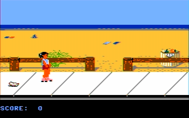
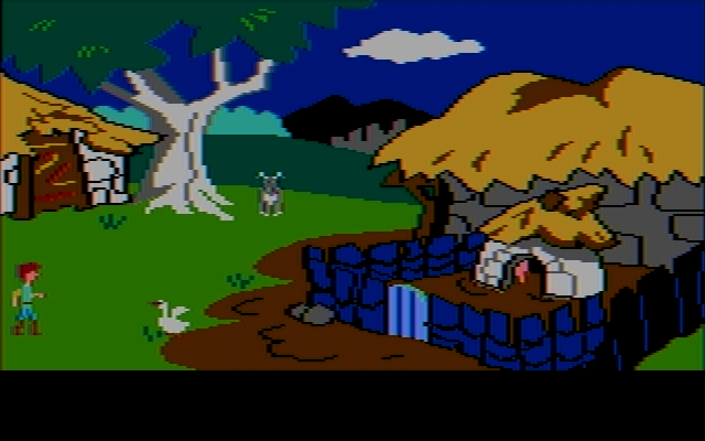
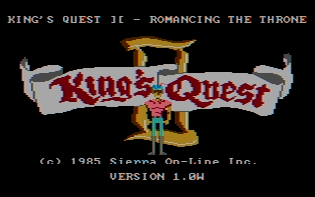
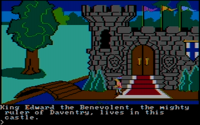
But it won't necessarily make for particularly pretty colors. In particularly, people will continue to pester the developers about brown being too greenish or red being too pinkish, depending on the hue setting. The most user-friendly approach would be to screw the standard and just make up a decoding matrix that produces pretty colors. Such a matrix would be in polar coordinate form:

R-Y: gain=2.00 angle=120°
G-Y: gain=0.67 angle=260°
B-Y: gain=2.00 angle=-10°

See pictures, all at a hue setting of ±0°. You would not need any fancy non-linear color correction either. That's actually the solution I would now favor, as there are no brownie points to be earned from following a 59-year-old standard as closely as possible.

Attachments

  • California Games.png
    Filename
    California Games.png
    File size
    31.9 KiB
    Views
    1347 views
    File license
    Fair use/fair dealing exception
  • The Black Cauldron.png
    Filename
    The Black Cauldron.png
    File size
    69.16 KiB
    Views
    1347 views
    File license
    Fair use/fair dealing exception
  • King's Quest II.png
    Filename
    King's Quest II.png
    File size
    46.37 KiB
    Views
    1348 views
    File license
    Fair use/fair dealing exception
  • King's Quest.png
    Filename
    King's Quest.png
    File size
    72.74 KiB
    Views
    1347 views
    File license
    Fair use/fair dealing exception

Reply 218 of 758, by VileR

User metadata
Rank l33t
Rank
l33t

"Pretty colors" is a rather subjective measure in itself, and if the qresult is cyan-colored grass (KQ1), bluish trees (KQ1, Black Cauldron), pastel-like yellows, etc., then I don't know how effective that would be in fending off user complaints.

[ WEB ] - [ BLOG ] - [ TUBE ] - [ CODE ]

Reply 219 of 758, by NewRisingSun

User metadata
Rank Oldbie
Rank
Oldbie

Well, it can still be optimized, of course. 😀 But you notice that the grass in King's Quest is the same color as Graham's pants in King's Quest II, which are cyan in RGB. The booter version of King's Quest translates the same RGB colors differently to composite colors than King's Quest II.

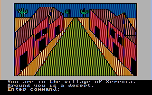
In the meantime, I have noticed that in addition to Microsoft Decathlon, Adventure in Serenia, the IBM PC port of Sierra's The Wizard and the Princess, is somewhat sensitive to the CGA revision used, assuming that I am applying the algorithms correctly.

Attachments

  • new.png
    Filename
    new.png
    File size
    21.51 KiB
    Views
    1320 views
    File comment
    with CGA part number 1501981
    File license
    Fair use/fair dealing exception
  • old.png
    Filename
    old.png
    File size
    22.76 KiB
    Views
    1320 views
    File comment
    with CGA part number 1804472 or 1501486
    File license
    Fair use/fair dealing exception