VOGONS


First post, by Kahenraz

User metadata
Rank l33t
Rank
l33t

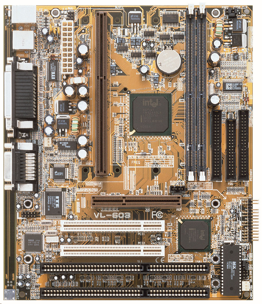
I have a FIC VL-603 motherboard with an odd capacitor attached at the top right corner. When received it, one of the leads had broken off and was floating. The only place it seemed capable of reaching was the edge of a SMD resistor at R288.

The system powers on fine with or without the capacitor connected at this point. I wasn't certain that this was a factory modification or that I had reattached it to the correct location so I have disconnected it. But I have since found photos of other boards online with this capacitor present. Unfortunately, none are close enough to identify where my detached lead is supposed to connect.

Does anyone have any information about this board or own one that can photograph where this is supposed to attach?

The attachment IMG_20211007_175556_resize_14.jpg is no longer available
The attachment IMG_20211007_175529_resize_10.jpg is no longer available
The attachment IMG_20211007_175438_resize_68.jpg is no longer available
Last edited by Kahenraz on 2021-10-07, 23:29. Edited 1 time in total.

Reply 1 of 12, by Namrok

User metadata
Rank Oldbie
Rank
Oldbie

I was trying to look this up, and I think it's a FIC VL-603 instead. Doesn't look like any of the Shuttle HOT-657V's google is turning up, and it has VL-603 printed below the AGP slot.

Also, the pictures I can find of it don't have a capacitor there. I'm not finding many, mind you. But I also can't help but notice that the capacitor in question looks nothing like the rest on the board either.

Win95/DOS 7.1 - P233 MMX (@2.5 x 100 FSB), Diamond Viper V330 AGP, SB16 CT2800
Win98 - K6-2+ 500, GF2 MX, SB AWE 64 CT4500, SBLive CT4780
Win98 - Pentium III 1000, GF2 GTS, SBLive CT4760
WinXP - Athlon 64 3200+, GF 7800 GS, Audigy 2 ZS

Reply 2 of 12, by Horun

User metadata
Rank l33t++
Rank
l33t++

That is a FIC VL-603 motherboard, not Shuttle. https://www.elhvb.com/mobokive/Archive/Fic/ma … -603/Vl-603.jpg
The Shuttle looks like this: http://www.amoretro.de/2013/01/shuttle-hot-67 … otherboard.html
I see many pictures of your board but only one shows that capacitor and the (-) lead that is disconnected should go to ground AFAIK.
Not sure why it was added unless some 3rd party Overclocker website recommended it (just a guess)

Hate posting a reply and then have to edit it because it made no sense 😁 First computer was an IBM 3270 workstation with CGA monitor. Stuff: https://archive.org/details/@horun

Reply 3 of 12, by Kahenraz

User metadata
Rank l33t
Rank
l33t

I made a mistake with this thread. I am also working with a Shuttle HOT-675V which looks almost identical and mixed them up when writing this.

It is in fact a FIC VL-603.

Reply 4 of 12, by Kahenraz

User metadata
Rank l33t
Rank
l33t

I'm measuring continuity with ground against the plated screw hole with both points of the capacitor if it did in fact connect to R288. Why would there need to be a capacitor between two points to ground?

There is a discrepancy though. There is a 0.6 ohm resistance on the resistor and 30 ohm on the VRM pad.

The attachment vl603_gnd.jpg is no longer available

Reply 5 of 12, by Kahenraz

User metadata
Rank l33t
Rank
l33t

I spoke to someone on eBay that has this board missing the capacitor. He says that his board is version 504. Mine is 501. This appears to be a bodge for *something* that was changed in a later revision.

I would like to document what this capacitor is supposed to connect to if it's possible to verify it on a board where it hasn't broken off.

Reply 6 of 12, by Horun

User metadata
Rank l33t++
Rank
l33t++
Kahenraz wrote on 2021-10-08, 00:46:

I'm measuring continuity with ground against the plated screw hole with both points of the capacitor if it did in fact connect to R288. Why would there need to be a capacitor between two points to ground?

There is a discrepancy though. There is a 0.6 ohm resistance on the resistor and 30 ohm on the VRM pad.

vl603_gnd.jpg

First observation: There is no way that was soldered to R288 at a refurb factory. Have never seen such bad soldering unless I did while drunk and maybe 30 years ago 😀
OK just saying that is not some genuine factory add-on or some genuine refurb plant that did that. The question is who did that and why ?
Some seller on Ebay may not know anything. If none of the long time guru's here never seen it then it is a very questionable thing...

Hate posting a reply and then have to edit it because it made no sense 😁 First computer was an IBM 3270 workstation with CGA monitor. Stuff: https://archive.org/details/@horun

Reply 7 of 12, by Kahenraz

User metadata
Rank l33t
Rank
l33t

That "bad soldering" is something I did a few years ago. I'm much better at it now and was hesitant to photograph it in the event that questions may be asked and I would have to admit to being responsible for it. I guess the secret is out. 😀

I have a proper microscope now and that would have helped to identify if that resistor is where it was broken off from but now I can't know for sure.

I have seen one other board with this same bodge but it's a sold listing on eBay so it's not unique to mine.

https://www.ebay.com/itm/254604491352

The attachment Capture.PNG is no longer available

Reply 8 of 12, by snufkin

User metadata
Rank Oldbie
Rank
Oldbie

Looks to me like someone was trying adding some input capacitance to that regulator. The main pad of the FDB603AL FET is the drain input, so probably connects directly to one of the inputs on the ATX power connector (maybe 5VSB). That pad of R288 is probably a convenient GND connection (looks like it's used to pull the CMOS power input to GND through a 10 ohm resistor). My guess is that source output of the FET ends up going through that diode next to it, which feeds the RAM voltage. That way, if the board is put in to standby then when the 3.3V supply turns off, the 5vSB can take over and maintain the RAM contents. Perhaps someone was having problems with the board not coming out of sleep and suspected the supply to the RAM wasn't stable, so tried adding the capacitor to try and smooth it.

I am of course assuming the board supports some sort of sleep mode.

Reply 9 of 12, by Kahenraz

User metadata
Rank l33t
Rank
l33t

That's an awfully specific analysis given such little information. Very convincing. I love it.

I understood the part about "fixes sleep mode" but the rest requires a monocle, a comfortable arm chair, and a slow but calculated nod in agreement.

I'll see myself out. 😀

Reply 10 of 12, by snufkin

User metadata
Rank Oldbie
Rank
Oldbie

If you're interested about it, you can check a few things. You've already got that the R288 pad goes to GND (you measured 0.6 ohm from there to the screw hole, which will be GND). The 30 ohm to GND that you measured on the Drain of the FET suggests that it might go to one of the pins on the ATX PSU connector, so you could measure the resistance to each of those pins and see if one's near 0, then look up what it is. That'll tell you which the input supply is. You can also check for a connection from the Source pin (the pin nearest the next thing that looks like a FET but is actually two face-to-face diodes) to either pin 1 or 3 of that couple of diodes next to it. Then from pin 2 of the diodes to one of the power pins on the SDRAM slots (I think the two pins nearest the edge of the board, 84 & 168 are both Vcc).

Working out what's connected to what always takes me ages, so it's all just a guess and there's a good chance I'm wrong. I've also seen a regulator in the same place on another board that was generating 3.3V for the whole board from the 12V supply. The board then had a separate mosfet elsewhere to switch the RAM between that 3.3V and a second 3.3V supply generated elsewhere from 5VSB that was used when the board was in sleep.

Reply 11 of 12, by Kahenraz

User metadata
Rank l33t
Rank
l33t

Why would a board be designed to generate 3.3V from 12V when 3.3V is already available from the ATX connector?

Reply 12 of 12, by snufkin

User metadata
Rank Oldbie
Rank
Oldbie
Kahenraz wrote on 2021-10-08, 12:31:

Why would a board be designed to generate 3.3V from 12V when 3.3V is already available from the ATX connector?

That is a really good question.

No idea.

Best theory I could come up with was that it allows for tighter control of the 3.3V. As far as I know there's no feedback to the ATX supply, so it can't compensate particularly well for any resistive losses between itself and the load. I suppose it could very gradually increase its internal 3.3V line as the current supplied goes up, but if it doesn't do that then as demand on the 3.3V goes up the voltage will start to drop (and that's separate from any ripple that smoothing capacitors would deal with). If the board has its own regulator then it can have a feedback/sense trace right by whatever's the biggest load, so the regulator can compensate to make sure the load actually gets 3.3V.