VOGONS


First post, by robbiesz

User metadata
Rank Newbie
Rank
Newbie

Hi

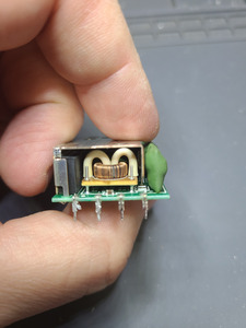
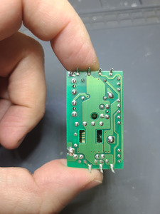
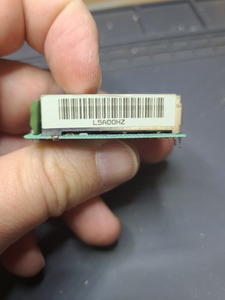
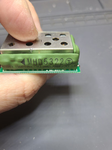
In an attempt to save a botched repair job, I am looking to identify (and somehow find a replacement to purchase of) this component: MHD5322 or MHD5322C

TL;DR: see pictures.

Backstory:
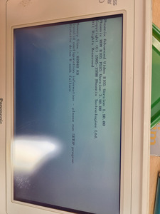
The laptop was/is a rare Raven RNC-3SX 386SX 20MHz machine (4MB RAM/60MB HDD). I found grand total of 1 link on google mentioning the brand and model. I have not been able to find anything more out about it.

It came to me broken. There were a ton of leaked smd caps on it. Unfortunately (and I have been banging my head against the wall since) I used a hot airgun to remove one of the caps. It was too tightly packed, and in the process, I applied too much heat to a hybrid/analog looking circuitry right next to the cap (see pics). The laptop has been even more broken since, not even a flash of lights.

After long months of google image searching I discovered that the laptop is a rebranded Panasonic Business Partner CF-370H6. Luckily, I found one for sale on ebay. I paid a fortune for that salvage laptop, and hoped that I could make 1 working out of the 2 broken laptops. After opening the Panasonic, I discovered that the mainboard is a different revision. I replaced the leaked caps and voila, the Panasonic booted.
Now I had a dilemma, leave the Panasonic working, take my winnings and go home.
Or unsolder that circuitry and see if that would make the Raven work again.

After much comtemplating I decided on the latter. I removed it gently and put it into the Raven (the component matched to other one exactly).

To my greatest surprise the Raven booted up just fine. I am extremely happy and sour at the same time. I need to find that component so both laptops can live again.

Sorry for lengthy story.

Would anyone happen to know what component this is and where on Earth I could get one? (I cant keep buying Ravens and Panasonic laptops for $$$ hoping that one would only have that part working)

Any help would be greatly appreciated!

Thanks for your interest and reading this!

Rob

Attachments

  • 20211217_232920.jpg
    Filename
    20211217_232920.jpg
    File size
    1.65 MiB
    Views
    780 views
    File license
    CC-BY-4.0
  • 20211217_232037.jpg
    Filename
    20211217_232037.jpg
    File size
    1.25 MiB
    Views
    780 views
    File license
    Fair use/fair dealing exception
  • 20211217_232005.jpg
    Filename
    20211217_232005.jpg
    File size
    1.31 MiB
    Views
    780 views
    File license
    Fair use/fair dealing exception
  • 20211217_232017.jpg
    Filename
    20211217_232017.jpg
    File size
    965.85 KiB
    Views
    780 views
    File license
    Fair use/fair dealing exception
  • 20211217_232030.jpg
    Filename
    20211217_232030.jpg
    File size
    1.28 MiB
    Views
    780 views
    File license
    Fair use/fair dealing exception

Reply 1 of 12, by vstrakh

User metadata
Rank Member
Rank
Member

Looks like a dc-dc converter, maybe worth probing the voltages and finding an alternative replacement for the whole module rather than keep looking for unobtanium?

Reply 2 of 12, by weedeewee

User metadata
Rank l33t
Rank
l33t

yep, open it up, identify the parts inside, trace out the schematic and build your own.

Right to repair is fundamental. You own it, you're allowed to fix it.
How To Ask Questions The Smart Way
Do not ask Why !
https://www.vogonswiki.com/index.php/Serial_port

Reply 3 of 12, by snufkin

User metadata
Rank Oldbie
Rank
Oldbie

Just to add, I'd expect the metal box (EMI shield) will have protected anything inside from too much heat, so components in there might still be ok. Possibly worth taking it off and having a look anyway, but it might need a fairly heavy soldering iron to melt the solder points.
More of a problem might be those 2 green things. They look to me like they're vertically mounted PCBs with a bunch of surface mount components, that have then been covered in some protective wrapping (heat shrink bag maybe?). If they got hot enough for any solder inside to melt then a component might have slipped down. Could be worth trying to slice one end of the cover and seeing if it can be removed.

I don't know the laptop, but if there's no external power brick, then there's a chance this is an AC-DC converter, so there could be mains voltages around.

Reply 4 of 12, by Thermalwrong

User metadata
Rank Oldbie
Rank
Oldbie

It does looks like the CF-370 uses a power brick like my CF-41, so it should be safe DC rather than mains voltage.
I think that disassembling the working module could go badly, especially with that weird green potted PCB on the side.
On the bad module (since swapping out it resolves the problem), maybe try disassembling that with removing the shroud to see if something's wrong under there. Those green potted components shouldn't have been damaged by heat? Surely the covering would've protected them.

On the working board. You could try running extension wires for the board-to-board connectors from that weird module (which does look like a DC/DC board to me) to the main PCB. Then you could probably probe around when it's on and see what voltages come out.

It looks like Panasonic were the ODM for several similar laptops - https://groups.google.com/g/comp.sys.tandy/c/ … /m/USB6-yNNsWMJ
The DEC 320P looks very similar I think?
(dang, the grid 1755 looks like my old sinclair PC200, do want)
I wonder if there might be another good parts machine available somewhere?

Reply 5 of 12, by BitWrangler

User metadata
Rank l33t++
Rank
l33t++

If I was gonna guess, I'd say batt voltage, wall adapter voltage and gnd/0V in... then 12V, 5V out plus... depending what doesn't have it's own power module... battery charge voltage and/or screen illumination and/or drive voltage out... unless it had sophisticated diagnostic feedback, I'd say it would attempt boot and fail if 12V was broken, saying drive error, if 5V broken, doornail dead, though mayyyybe screen would light. if it output nothing but crunched the drives then screen voltages (and may show something on external monitor)

edit: IDK how easy you'd find it to hook up the dead module for a test, but if you do, try putting power to the battery terminals, whatever voltage the battery put out, there's a small chance that it's only dead through adapter voltage input.

Unicorn herding operations are proceeding, but all the totes of hens teeth and barrels of rocking horse poop give them plenty of hiding spots.

Reply 6 of 12, by snufkin

User metadata
Rank Oldbie
Rank
Oldbie
Thermalwrong wrote on 2021-12-18, 19:04:

It does looks like the CF-370 uses a power brick like my CF-41, so it should be safe DC rather than mains voltage.

Good to hear. I just started playing with/attempting to repair a Toshiba 110CT that has the mains AC-DC adapter built in, so I thought it best to check before poking around.

I think that disassembling the working module could go badly, especially with that weird green potted PCB on the side.
On the bad module (since swapping out it resolves the problem), maybe try disassembling that with removing the shroud to see if something's wrong under there. Those green potted components shouldn't have been damaged by heat? Surely the covering would've protected them.

Definitely only start attacking the dead module, I didn't mean to imply doing anything to the working one. I'll be surprised if any components have actually been heat damaged, but was speculating that some solder may have melted and allowed a component to slide (especially if the cover was pushing on it), either causing a short or a disconnect, hence suggesting pull back that cover. If there's nothing obviously wrong, then have a go at measuring the input and output voltages on the working module to find out what it should do. Having a working module makes troubleshooting a lot easier.

Reply 7 of 12, by robbiesz

User metadata
Rank Newbie
Rank
Newbie

Thanks for the replies. I figured it would be a DC-DC converter. The photos are of the working one, the other one I already opened. I got as far as confirming all the individual components on it were fine. I did not even attempt to break off the green coating as I am sure there is nothing underneath that I would be able to service or find replacement parts for.

However one of your replies pointed me to another clone/odm which has a nice repair thread on vcfed. This opened some new ways for me to try to acquire a working dc dc converter.
For those who are interested, the input voltage is 16V and the output are 5V and (minus) -22V.

Thank you for all your comments. Very helpful!

Reply 8 of 12, by BitWrangler

User metadata
Rank l33t++
Rank
l33t++

Please share the link for ppl digging up this thread later, and myself, got a weirdy 386 with converter probs I'm "missing" something on, keep shelving it until I have refilled the patience tank.

Unicorn herding operations are proceeding, but all the totes of hens teeth and barrels of rocking horse poop give them plenty of hiding spots.

Reply 9 of 12, by robbiesz

User metadata
Rank Newbie
Rank
Newbie

Certainly! I wasn't sure if links to vcfed were allowed: https://www.vcfed.org/forum/forum/genres/tand … o-got-my-2810hd

Both the Tandy 2810HD and DECpc 320p look like my CF-370, so I have new search terms to use on ebay.

Also, apparently there is a schematic available for the Tandy 2810HD (which I am searching for right now).

Reply 10 of 12, by snufkin

User metadata
Rank Oldbie
Rank
Oldbie
robbiesz wrote on 2021-12-19, 03:42:

I did not even attempt to break off the green coating as I am sure there is nothing underneath that I would be able to service or find replacement parts for.

You might be surprised. I think it looks like it's just a normal PCB with SMD resistors/capacitors/etc., that's been covered up to stop accidental shorts. Might be wrong though. It's already broken, and you've got a plan for a replacement, so if you've got a bit of time it might be interesting to have a go at hacking that cover off. If nothing else, it might help document it for someone else.

Reply 11 of 12, by vstrakh

User metadata
Rank Member
Rank
Member
snufkin wrote on 2021-12-19, 20:17:

it might be interesting to have a go at hacking that cover off

That cover looks and feels just like a ceramic, or at least some powdery clay baked to the state of ceramic.
Hacking that off would mean destroying a substrate - likely also a plain old white ceramic die/plaque.

Reply 12 of 12, by pentiumspeed

User metadata
Rank l33t
Rank
l33t

This is not ceramic, this is very hard glue and gets broken apart like shattered dish if you attempt to chip away at it. It is not usually the issue. The board needs to looked at before suspecting the thick film hybrid circuit boards. These thick film technology is made of white ceramic board made of silver tracks, rectangles of black, thick film printed surface as resistors, rest is SMD capacitors and 3 terminals transistors, occasional SMD IC. Cannot be repaired of these.

Like this: https://images.app.goo.gl/K2V1a1XVdqxEcEUg6

Cheers,

Great Northern aka Canada.