VOGONS


First post, by vejvycz

User metadata
Rank Newbie
Rank
Newbie

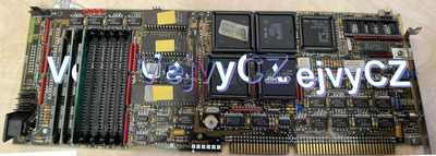
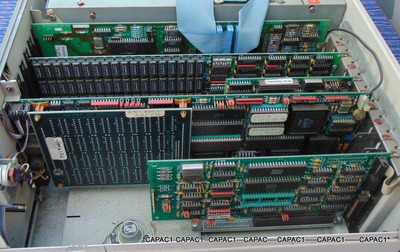
Hi, I'd like some advice here. I have this board LEANORD C 1792D with a processor 286, it is a board to the ISA slot and so it requires an ISA board, which I made and it is verified that it works. However, when testing the LEANORD board only with the graphics and keyboard connected, there is no video signal on the monitor. I didn't find anything on this board on google, I don't know if, for example, all ram slots must be fitted, or maybe connect a battery somewhere, etc. It would help me a lot if someone could find a manual at home and maybe other information, I'd like a CPU board 286 launched.
Thank you.
https://uloz.to/file/WjTUZTcoUvaY/leanord-c-1 … HH1rQWcqGxmLj==
https://uloz.to/file/CD65jF90R8y9/leonard-zip … USvLJkyHQL0MN==
Diplej post:
https://uloz.to/file/WlQKTTEUoTlW/img-0620-mp … TAlAaR4oGD2Lt==
https://uloz.to/file/mIU1ivDjvFAw/img-0618-mo … UO1rx9jrQSwAt==
https://uloz.to/file/wormoD3d44Il/img-0619-mp … TDgGHIDqmZ3Mt==

So I played with it a bit. It is not possible to read the FW of the three eeproms under each other perfectly, because the programmer reads it probably too fast and the eeproms are very slow ....
The second thing I found out where to connect the battery and identified the correct polarity and found the right crystal and IC where it should be on leg 14 (positive voltage) and on leg number 7 should be GND (ground), there was a voltage for a while, but when I went about a while later to measure the battery, so the voltage was only 2.42V (I used cr2025 and the classic diode 1N4148, there was a slight loss of voltage behind the diode, but it was nothing extreme, the diode is there because there was probably an original battery and my point is not to put voltage into the classic battery, because otherwise the battery could explode. The display posts, but the boot doesn't get very far ....
Do you think it will go live at all ??? I'd like it to work, but it's probably not very real.
I uploaded to the web various videos from the post display and another photo incl. battery installation.
BATTERY:
https://uloz.to/file/59CfOsh7OcWe/leanord-286 … zEarF1lETSyAN==

Last edited by vejvycz on 2022-02-19, 19:04. Edited 4 times in total.

Reply 1 of 12, by snufkin

User metadata
Rank Oldbie
Rank
Oldbie

Looks to me like the silkscreen says Leanord, so maybe it's from something like this: https://www.old-computers.com/museum/computer … asp?st=1&c=1013

Even if right, doesn't really help much since there doesn't seem to be much information about it.

[edit: hope you don't mind, but I've taken 3 of the photos in that .zip file and stitched them together so it'll be easier for others to have a look at the board. I made the blue in each layer transparent to keep as much of the board visible as was in the photos. If you're not happy with that I can take it down again, but I thought it'd be good to let others see the board.]

Attachments

Reply 3 of 12, by snufkin

User metadata
Rank Oldbie
Rank
Oldbie

I'm pretty sure it is the board from a Leanord Elan. There are some small pictures here: https://www.old-computers.com/museum/photos.a … t=1&c=1013&st=1 where you can see the cards in the case. It looks like the video was either Hercules or CGA, so maybe it'll depend on the graphics card that you're using. One of those 4 pin headers either side of J10 might be a speaker header, so maybe you'll get some beep codes if you connect a speaker from pin 1-4. Although from the comments on that site it wasn't a standard AMI/Award/Phoenix one, so who knows if it gives beeps or not. A POST card might help.

Found some more pictures of the Elan here: https://aukro.cz/pocitac-starozitny-leanord-e … en&_x_tr_pto=sc

Leanord_Elan_Inside.jpg
Filename
Leanord_Elan_Inside.jpg
File size
93.59 KiB
Views
363 views
File license
Fair use/fair dealing exception

Although looking at it closer, it's not quite the same as yours, with the chipset and BIOS chips not in the same place. LEDs look the same, mounting holes for the (I guess) RAM expansion and the headers for cable connections.

Reply 4 of 12, by weedeewee

User metadata
Rank l33t
Rank
l33t

Just for starters, it's a 286 so 30 pin simms should be placed in pairs.

Right to repair is fundamental. You own it, you're allowed to fix it.
How To Ask Questions The Smart Way
Do not ask Why !
https://www.vogonswiki.com/index.php/Serial_port

Reply 5 of 12, by snufkin

User metadata
Rank Oldbie
Rank
Oldbie
weedeewee wrote on 2022-02-18, 21:50:

Just for starters, it's a 286 so 30 pin simms should be placed in pairs.

Ah, that's an artifact of how I stitched the photos together which makes it look like there are 3 simms fitted, when there are 4 in the original photo. It's a parallax/perspective problem with things that have height.

Reply 6 of 12, by Horun

User metadata
Rank l33t++
Rank
l33t++
vejvycz wrote on 2022-02-18, 18:44:

All right, I don't mind, I had a photo of the whole thing somewhere, but I didn't want to take it now, if I needed to take the whole picture tomorrow ...

Thanks and Please do not watermark it across the actual board. Makes it harder for anyone to help you 😀

Hate posting a reply and then have to edit it because it made no sense 😁 First computer was an IBM 3270 workstation with CGA monitor. Stuff: https://archive.org/details/@horun

Reply 8 of 12, by vejvycz

User metadata
Rank Newbie
Rank
Newbie
snufkin wrote on 2022-02-18, 21:24:
I'm pretty sure it is the board from a Leanord Elan. There are some small pictures here: https://www.old-computers.com/museum/p […]
Show full quote

I'm pretty sure it is the board from a Leanord Elan. There are some small pictures here: https://www.old-computers.com/museum/photos.a … t=1&c=1013&st=1 where you can see the cards in the case. It looks like the video was either Hercules or CGA, so maybe it'll depend on the graphics card that you're using. One of those 4 pin headers either side of J10 might be a speaker header, so maybe you'll get some beep codes if you connect a speaker from pin 1-4. Although from the comments on that site it wasn't a standard AMI/Award/Phoenix one, so who knows if it gives beeps or not. A POST card might help.

Found some more pictures of the Elan here: https://aukro.cz/pocitac-starozitny-leanord-e … en&_x_tr_pto=sc
Leanord_Elan_Inside.jpg
Although looking at it closer, it's not quite the same as yours, with the chipset and BIOS chips not in the same place. LEDs look the same, mounting holes for the (I guess) RAM expansion and the headers for cable connections.

Thank you very much, when I come home I'll take a look.

Reply 9 of 12, by vejvycz

User metadata
Rank Newbie
Rank
Newbie

I tried to read three chips that have the transparent glass on the eeprom memory. Unfortunately, I'm not a programmer, so I can't tell if the source code is okay or corrupt. Please info if I saved it to the correct files. Here is the link to the file:https://uloz.to/file/ZlCRsC9NBKlI/286-fw-cipy … 3t1Ax05IGV4BN==

Reply 11 of 12, by vejvycz

User metadata
Rank Newbie
Rank
Newbie
snufkin wrote on 2022-02-18, 21:24:
I'm pretty sure it is the board from a Leanord Elan. There are some small pictures here: https://www.old-computers.com/museum/p […]
Show full quote

I'm pretty sure it is the board from a Leanord Elan. There are some small pictures here: https://www.old-computers.com/museum/photos.a … t=1&c=1013&st=1 where you can see the cards in the case. It looks like the video was either Hercules or CGA, so maybe it'll depend on the graphics card that you're using. One of those 4 pin headers either side of J10 might be a speaker header, so maybe you'll get some beep codes if you connect a speaker from pin 1-4. Although from the comments on that site it wasn't a standard AMI/Award/Phoenix one, so who knows if it gives beeps or not. A POST card might help.

Found some more pictures of the Elan here: https://aukro.cz/pocitac-starozitny-leanord-e … en&_x_tr_pto=sc
Leanord_Elan_Inside.jpg
Although looking at it closer, it's not quite the same as yours, with the chipset and BIOS chips not in the same place. LEDs look the same, mounting holes for the (I guess) RAM expansion and the headers for cable connections.

I have made a post display on the ISA board I made, but I haven't set the jumpers correctly yet and somehow I can't figure out how to set them correctly, I made the ISA board according to the instructions from one person from Russia, it was made by more people and it is verified that it works, but there is no manual or description of the jumpers, so it is a trial and error method, in the afternoon I will upload detailed photos to the website of both the 286 and the ISA boards ...