First post, by Kahenraz

Rank
l33t
- Rank
- l33t
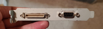
I know that this is some kind of flat panel connector. Does anyone recognize it or know if there is an adapter for it?
I know that this is some kind of flat panel connector. Does anyone recognize it or know if there is an adapter for it?
Didn't count the pins but it looks like a 26pin DFP connector.
Looks way to big to be a DFP connector IMHO, looks more like some kind of mini centronics lookalike connector.
chiveicrook wrote on 2022-03-26, 07:32:Looks way to big to be a DFP connector IMHO, looks more like some kind of mini centronics lookalike connector.
You're right. I counted and it appears to be 40pin?
Maybe knowing/seeing the card would help?
Looks like 40 pin (20 top and bottom). Thought it might be the SGI flat panel connector, but that's 36 pin. What card is it on?
It seems to be an OpenLDI connector for the SGI 1600SW display.
What is the graphic card ?
I don't have a photo of the card at the moment. I managed to figure out that it's an old VESA standard called PanelLink, of the 40 pin variety. This card is labeled "Wincor Nixdorf" is from their POS line of computers.
Am adapter exists, but it lives in the "if you have to ask the price" category.
https://www.reteccom.com/en/home/products/dis … ms/01750078100/
I don't know what the smaller connector is for. Is there a way to safely test if the pins contain a VGA signal?
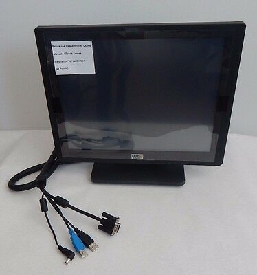
Here is a photo of the LCD for their POS system. I guess this is a form of DRM, so that you must buy their monitor in the event of a failure. I can't get a good look at the dsub connector on some of their screens, but it might stay be modified as primitive DRM.
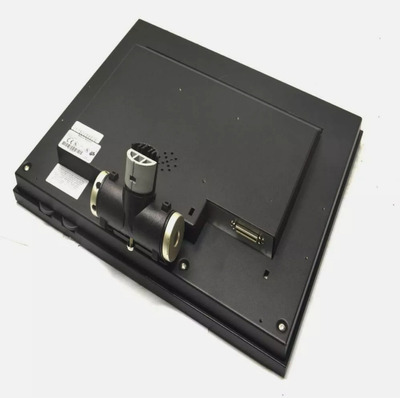
Bringing up the level on the photo of the connectors then it looks like a dsub-9. Tiny bit more information here: https://www.manualslib.com/manual/889278/Winc … -2.html?page=29
Kahenraz wrote on 2022-03-26, 10:21:I don't know what the smaller connector is for. Is there a way to safely test if the pins contain a VGA signal?
Measure the signals with an oscilloscope.
Right to repair is fundamental. You own it, you're allowed to fix it.
How To Ask Questions The Smart Way
Do not ask Why !
https://www.vogonswiki.com/index.php/Serial_port
weedeewee wrote on 2022-03-26, 11:34:Measure the signals with an oscilloscope.
I bought a Rigol DS1054Z oscilloscope some time ago for tinkering, but I've never used one before and have no idea how to do it. Would you be so kind as to offer a for-dummies guide on what to do?
It's been one of those things that I got for a bigger repair I had hoped to use as a learning experience, but it got shelved, and so did the scope. It's very imposing and I'm afraid to break the darn thing by looking at it the wrong way.
Just found a possible pinout: https://www.manualslib.com/manual/814614/Winc … ?page=51#manual
It's possible that RX[0,1,2,C][N,P] pins are the 3 pairs and clock for a single link DVI-D/HDMI. Then there are some +5V and +12V connections (monitor powered over the connector maybe?), something labeled FPEN (Flat Panel ENable? maybe a monitor detect pin, pulled low by the monitor?), HUOUT (no idea), RxD1 and TxD1 (some sort of serial connection/ maybe something like DDC?).
So there's a small chance of being able to make a passive adapter to DVI, although reading supported resolutions probably won't work. And it's possible the card won't output anything if it doesn't get the right signals from the monitor on TxD1. And it looks like that dsub is a serial port.
The manual in my previous post was for the BA73A-2, which doesn't have a pinout, but does say it supports EDID. The manual at the top of this post is for the BA73A, but it doesn't mention EDID. So it's possible that some of the connector pins marked NC have been used for the DDC connection.
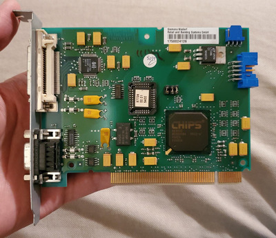
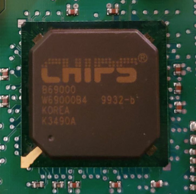
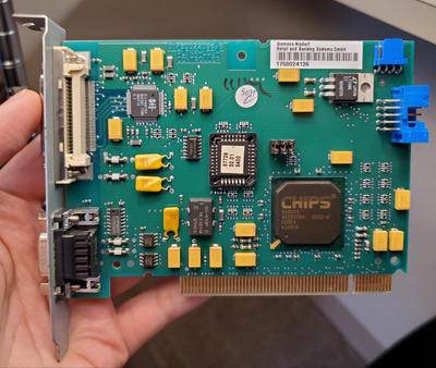
Here is a photo of the card. I bought it out of curiosity to see how a Chips and Technologies 69000 performed.
PanelLink is supposedly very closely related to OpenLDI, but unfortunately not enough to be able to just hook up a 1600SW.
I have some 1600SWs and spotted one of these C&T cards with PanelLink (an older one) so grabbed it. Unfortunately thought the card works fine via VGA (and on 1600SW via VGA through an SGI Multilink), it doesn't give output when connected directly.
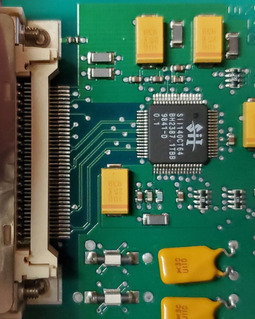
I may be misreading it, but I think the SiI140 output is DVI compliant. I found a partial datasheet for it, whilst cursing whoever thought mixing i, I and 1 in a part number was a good idea. At least they didn't use l.
[that's SiI140 with a lower case i, upper case i and number 1]
Would need a better photo of the PCB, front and back, around the connector and the SiI chip to confirm, but it looks like that previous pinout in the manual I found matches. Looks like that 4 pin connector on the top edge is for a speaker input and should wire through to pin 1 (HUOUT) on the main output, and would then go to a speaker in the screen (think of the beep from an ATM).
The dsub has an rs232 line receiver next to it, so is probably a COM port, which matches the manuals (COM6). It looks like the Tx and Rx pins in the 40 pin connector are also a serial port, the manual says COM5. Not sure where they'd get -ve voltage supply from, but maybe they just use 0-5V signalling.
Unsure about any sort of DDC / monitor detect connections. So it does look like it'd be possible to make up an adapter to connect a DVI monitor, but there could be issues around getting drivers to output anything. It looks like the Nixdorf system had jumpers on the motherboard to set the display type. The manual doesn't describe that jumper block on this card, it only says that B1 should be open and B2&3 closed (B1 closest to the BIOS chip).
You might be able to take the DVI signal from the conveniently placed solder points between the flat panel connect and the SiI140.
snufkin wrote on 2022-03-28, 10:12:I may be misreading it, but I think the SiI140 output is DVI compliant. I found a partial datasheet for it, whilst cursing whoever thought mixing i, I and 1 in a part number was a good idea. At least they didn't use l.
[that's SiI140 with a lower case i, upper case i and number 1]
I had the same experience with their storage controllers. For years I thought it was SiL (Silicon Logic) when it was in fact Sii (Silicon Image). That's some brain damaged brand marketing there.
snufkin wrote on 2022-03-28, 10:12:Would need a better photo of the PCB, front and back, around the connector and the SiI chip to confirm, but it looks like that previous pinout in the manual I found matches.
Here are some higher resolution photos of the front and back of the card. VOGONS seems to recompress them, so it's difficult to share as t the original quality.
I've ordered some solderable DVI connectors in anticipation. I'll definitely try this if we can find the right pins to test.
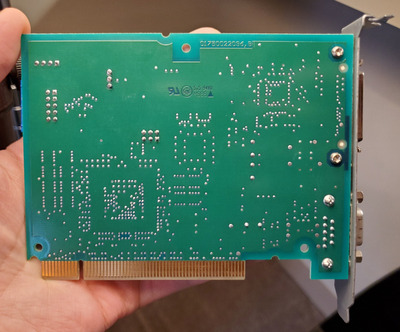
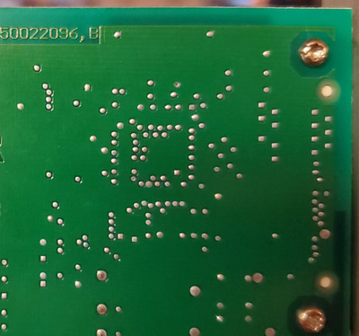
Boo, they've used internal layers for routeing. It looks like the connector pinout I found is close, but not the same. The DVI pairs are all the right number of pins away from each other, but not in the right order. Have you got a multimeter you can do a bit of tracing with? In particular, I think it'd help to orient things if we can find where on the connect the speaker signal is (HUOUT). I think there will be a short between pin 4 on the 4 pin header on the top edge of the board, and one of the pins on the 40 pin connector. It might be on one of the pins at the end of the connector, or it might be around pin 14 or 26.
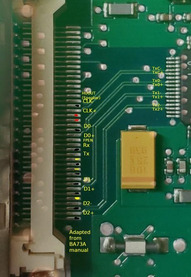
I've sketched out how the connector might be wired, based on lining up the order to the DVI pairs on the SiI140 and the BA73A manual. To check if it's right then you as well as trying to check the HUOUT pin, you can also check if the grounds, +5 and +12 supplies are in the right place. There are more tracks routed on that connector than the pinout I found, so some of those could be monitor detect stuff. Might be worth checking for connections between them and the vias around the bottom-right corner of the B69000 (that's where the DDC clock and data pads are).
I also noticed that everything was routed internally. This card is engineered like a tank.
