VOGONS


First post, by Bernkastel7734

User metadata
Rank Member
Rank
Member

Hello,
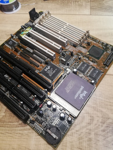
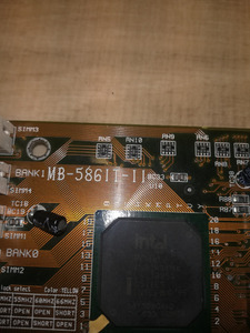
I have been trying to fix this socket 7 motherboard. It seems not to be part of ultimate retro, but it's name is 'MB-586IT-II' and according to google it was made by Expen Tech.
I got two problems with it:
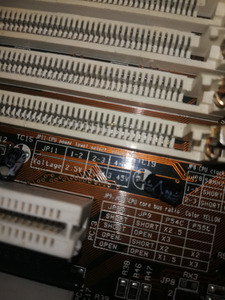
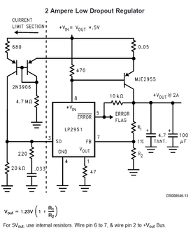
1) Someone stole voltage regulator mosfet from that motherboard. On it's silkscreen there is mentioned 2,5V 3,3V and 3,5V which seems like typical set for Pentium CPUs. I have no idea what part was there. Is there like universal set of suitable power transistors I can soldier there and expect it to work?
2) It seems to have some weird resistance between 5V and GND of 36,6 Ohm. Not a dead short but it seems odd. I have checked all capacitors and IC's for shorts and they all seem good. When I power that board nothing seems to get quite hot, nor explode. Also PSU with short detection seems not to have problem with that. Weird.

Attachments

Last edited by Bernkastel7734 on 2022-08-15, 21:25. Edited 1 time in total.

Reply 1 of 12, by Bernkastel7734

User metadata
Rank Member
Rank
Member

Oh, and don't look at that capacitors. I was looking for a shorted one.

Attachments

Reply 2 of 12, by DerBaum

User metadata
Rank Oldbie
Rank
Oldbie

Are you sure that the part was desoldered?
It looks like this version of the board is single voltage (no MMX cpu). The missing parts around Q5 are for the second voltage.
I have a Board where it is the same. My revision doesnt support mmx and similar parts are missing. Another revision supports MMX and has all the missing parts.
On my board are also bridged (soldered) Jumpers like on yours. So you cant switch the voltages.

Forget what i said... I just saw the second missing regulator (Q4)... Sorry.

FCKGW-RHQQ2

Reply 3 of 12, by Bernkastel7734

User metadata
Rank Member
Rank
Member
DerBaum wrote on 2022-08-15, 21:35:

Forget what i said... I just saw the second missing regulator (Q4)... Sorry.

Also I have checked on the socket itself- insted of 3.3V there is like 0.2V

Reply 4 of 12, by andyc

User metadata
Rank Newbie
Rank
Newbie

Hi! Did you figure it out? I found the same board but in green solder mask and it came with a dead Mostek D45H1A PNP transistor in the Q4 spot and Q3 missing from the factory. I don't think it's the original transistor as there is flux residue on the back side and it's clearly been replaced. Also, shouldn't there be a MOSFET there instead of a PNP?

Reply 5 of 12, by Bernkastel7734

User metadata
Rank Member
Rank
Member

Hi, frankly speaking I had no time for long investigation over it. It is on the list to fix in the future, so if I find anything interesting or usefull I'll let you know.

Reply 7 of 12, by snufkin

User metadata
Rank Oldbie
Rank
Oldbie

PNP could be ok depending on what U18 is. I can't find what device has the 51A-5 marking, but if U18 is an LP2951 then here's an example circuit from a datasheet for it:

LP2951_HighCurrent.png
Filename
LP2951_HighCurrent.png
File size
53.44 KiB
Views
557 views
File license
Fair use/fair dealing exception

As Vout on the LP2951 increases then the current coming in to the device through Vin increases, which means more voltage is dropped across that 470 ohm resistor. Lower Vin also means a lower voltage at the base of that external PNP transistor, so more current can flow through it, which will increase the voltage at the circuit output. That increases the voltage at the FeedBack input. All that carries on until the voltage at the FB input equals 1.23 volts (datasheet says this might actually be anything between 1.2V and 1.26V). The output voltage to get 1.23V at FB is set by R1 and R2. I guess that's what JP11 sets.

Mind that whatever PNP transistor is used needs to be able to handle the current (that D45H1A should have been ok) and will need a heatsink. TO220 temperature rise from junction to ambient without a heatsink will be something over 60C/W. If the CPU draws 2 Amps at 3.3V then that PNP will be burning (5V-3.3v) * 2Amps = 3.4Watts. So without a heatsink the transistor would need to get up to around 200C and it'll fail.

If you've got a multimeter to hand you could try to start working out what connects to what and see if it looks anything like that example circuit.

Reply 8 of 12, by majestyk

User metadata
Rank Oldbie
Rank
Oldbie

They also have this design in the datasheet (for the 51-N)

reg_appl.JPG
Filename
reg_appl.JPG
File size
51.42 KiB
Views
533 views
File license
Public domain

https://www.ti.com/lit/ds/symlink/lp2951-n.pd … google.com%252F

Could not find anything about the "-A" variant...

Reply 9 of 12, by Sphere478

User metadata
Rank l33t++
Rank
l33t++

Suggest checking out calamitylime’s solution to a linear regulator replacment using a murata.
Re: vrm module project thread roundup, share ideas, make new designs

It may be easier to just power it externally using a better psu than a linear regulator.

The tweakers under pcb projects in my sig may be of interest. They have taps for vcc3 and vcc2

But I also underStand if you want origional and a low speed socket 7 build. Totally legit 😀 in which case, of course just figure out original part numbers and order them.

Personally, I’d go for something like calamitylime did.

Sphere's PCB projects.
-
Sphere’s socket 5/7 cpu collection.
-
SUCCESSFUL K6-2+ to K6-3+ Full Cache Enable Mod
-
Tyan S1564S to S1564D single to dual processor conversion (also s1563 and s1562)

Reply 10 of 12, by snufkin

User metadata
Rank Oldbie
Rank
Oldbie
majestyk wrote on 2022-11-23, 15:56:
They also have this design in the datasheet (for the 51-N) reg_appl.JPG […]
Show full quote

They also have this design in the datasheet (for the 51-N)
reg_appl.JPG

https://www.ti.com/lit/ds/symlink/lp2951-n.pd … google.com%252F

Could not find anything about the "-A" variant...

True. Looks like it follows the same sort of principle of using a resistor on the Vin input and the current going in to Vin (which is controlled via the resistor on Vout) to control the voltage of the gate, to control the output voltage of the FET. With the output voltage fixed at 5V using the internal feedback resistors of the '51 (using Sense input and then connecting Vtap to FB). I've got a vague feeling that around this time that P-FETs tended not to have very good current capabilities and using a PNP might have allowed for higher current CPUs.

I suppose my point was that a PNP could work, so there's no reason is has to be a FET. Also that the transistor isn't being used as part of a switching regulator but more like a linear regulator, which means the power burnt will be higher, so a heat sink will almost certainly be needed to stop any replacement burning out immediately (it looks like there's space for one marked on the silkscreen). Without having another board to check on what components were there originally then it might be possible to work out what will work based on how it's connected together and what the resistor values are.

If it is connected similarly to either of the example circuits then I'd guess whatever transistor used will have to have a Vbe on/Vth that fits with the Rin and Rout connected to Vin and Vout on the '51. E.g. if Rout is very large then not much current will flow, and if Rin is small then Vin might not drop enough to turn on some transistors at all. Equally, if Rin is very large and Rout small then even tiny changes in Vout could cause large swings in Vin and the output of the circuit be unstable. But now that's heading further in to analog stuff.

Reply 11 of 12, by andyc

User metadata
Rank Newbie
Rank
Newbie

@snufkin
It looks similar and I think the pinout matches except the R1 and R2 formula does not match what I see on the board when I change jumper settings for different voltages. I will check more carefully under the microscope and with a better meter.
It did have a pretty large heatsink, as large as the outline on the PCB.

After some googling I found a thread on a russian forum that mentions another Expen Tech board labeled "MB-586-IT/CMD 646" and they mention that it has a D45H2A PNP for the regulator so i'm guessing the part was indeed correct. According to the datasheet the D45H2A and D45H1A are pretty similar, with the D45H2A part having a higher hFE. How would hFE influence it under this application? Should I look for the D45H2A part or an equivalent instead of the 1A?

I'll check my stash and see what BJTs I can find and post back the results.

Since it was already on the bench, I thought I'd dump the BIOS and check it out with modbin. I found an interesting "quirk". The BIOS singon message correctly states "MB-586IT-II i430HX" but the BIOS ID is 2A5KFE79C which would suggest an Ali chipset...

Attachments

  • Filename
    modbin.png
    File size
    9.98 KiB
    Downloads
    No downloads
    File license
    Public domain

Reply 12 of 12, by snufkin

User metadata
Rank Oldbie
Rank
Oldbie
andyc wrote on 2022-11-24, 11:06:

According to the datasheet the D45H2A and D45H1A are pretty similar, with the D45H2A part having a higher hFE. How would hFE influence it under this application? Should I look for the D45H2A part or an equivalent instead of the 1A?

From the datasheets I've found there are a few other differences as well (e.g. max current, Collector-Emitter breakdown voltage, other stuff). That said, I'd guess either would do. If hFE is too high then the output might be unstable, as it'd mean that the output voltage would be very sensitive to small changes in the current flowing through the '51. But I don't think there's enough of a difference to really matter. Datasheet for the H1A includes a graph showing hFE peaking at about 350 at low currents (0.15A collector current), dropping to about 70 at 10 Amps, so the sensitivity already changes quite a lot depending on the load.

I should mention that my analog knowledge is poor, so I may have missed something important.

I'd give it a try, starting without the CPU fitted. Stick a resistor of some sort (330 ohm maybe) between the output and ground as a tiny load, then measure the voltage. If you've got access to an oscilloscope then you can check how stable the output is. If it all looks ok, then try with a CPU.