Reply 20 of 36, by TheMobRules
kinetix wrote on 2023-07-29, 18:53:in my opinion, something is wrong in the jumpers settings documentation for 3.45v. I´ve been trying to find the correspondences to setting as voltage, cache type and multiplier, on both boards, the same. Unfortunately, I did not write down the configuration the board (both) had before changing it. I'm pretty sure I had it 20 years ago with that Am5x86. It would have been nice to have a "known" functional reference. and that is what I have been trying to find, the jumper configuration of those, anyone, who have one of those 3.45v processors installed on this board.
Yeah, considering that both the Intel and AMD DX4 variants support the VOLDET pin I don't understand why they would do it differently. I have another SiS471 board, the ASUS VL/I-486SV2GX4 which implements this feature in the following way: there is a jumper that allows you to connect the VOLDET pin of the CPU to the input of a 7407 buffer. The output of this 7407 is connected to the gate of the MOSFET, the drain is connected to +5V and the source is connected to the regulator output.
With the jumper cap on, if you use an Intel/AMD 3.3V CPU (which have the VOLDET pin connected to GND), the output of the 7407 will be low, so the MOSFET will be OFF and the regulator output remains at 3.3V. If you use a 5V CPU, the VOLDET pin is floating and the 7407 input is pulled to +5V through a resistor, so the gate is high and the MOSFET turns ON and the source is at +5V, effectively shorting the regulator output to provide +5V to the CPU.
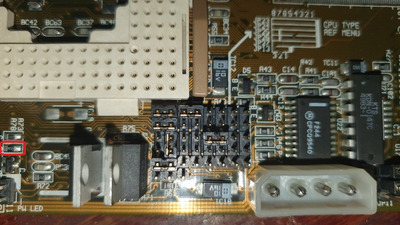
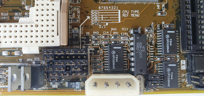
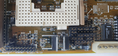
Based on what I was able to test on the VI15G with my multimeter, the equivalent jumper in this board would be JP25 pin 3 (CPU VOLDET) and pin 4 (input "3A" of the 7407 at the corner of the board, near the cache tag chip). The "3Y" output of the 7407 is, as expected, connected to the MOSFET gate. So it's strange that you get 3.45V without the CPU installed, unless something else is grounding VOLDET, but there may be slight differences between your board and mine.
But if you're interested in knowing what each of the jumpers in the configuration table does, here's what I was able to find by poking around with a multimeter for Intel/AMD DX-type CPUs (again, keeping in mind my board and yours may have differences and that I can't do voltage checks on my 5V-only board):
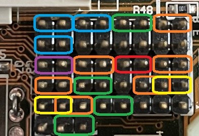
- BLUE jumpers are common for all DX-type CPUs
- GREEN jumpers are for SL-enhanced CPUs (i.e. with power management features)
- YELLOW is for L1 WT cache, ORANGE is for L1 WB cache (obviously these two are mutually exclusive, it's either one or the other)
- RED is for voltage auto-detection, as I mentioned above
- PURPLE controls the internal multiplier for DX4-type CPUs, open sets 3x while closed sets 2x (but for 5x86, you get 4x instead of 2x!)
As for the other jumpers on the table:
- JP9 and JP10 set the "trap" to program the SiS chipset depending on the CPU type (for Intel/AMD, JP9 is always 1-2 and JP10 is 2-3 for CPUs with L1 WB cache, 1-2 for regular L1 WT)
- JP16: this one I am unable to find out. It is unpopulated on my board, but it appears to be used to set the SMOUT1 pin of the SiS chipset (#58) LOW through the 7407, not sure what this does really