I'm back trying to get an old Panasonic/Matsushita CR562b working and have hit a problem with the read head. To fix earlier problems I've made a wire mod to reconnect the 12V on the top side of the PCB (flexing of the molex connector broke the PCB track) and replaced the cable linking the main PCB to the front panel to make the eject button reliable.
The tray now ejects properly and the read head seeks and tries to focus, with the laser on. The problem is that the disk doesn't spin up. I'm pretty sure that this is a problem with the read head and not the main disk motor. I've connected the whole head+motor assembly from the non-working 562 to the PCB of a working one and it has the same not-spinning problem, so the problem is somewhere in that assembly. I took the motor out of the broken 562 and put it in the working one and it spins up fine. So I don't think it's the motor, which only leaves the read head.
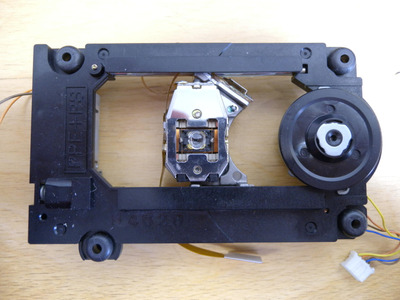
I guess there's some part of the read head that monitors the linear speed of the disk, and the servo controller on the PCB uses that to control the disk motor. There are two flat flexible cables (4 pin and 11 pin) connecting the read head to the PCB. They both look ok and I've tried testing continuity as best I can between the end of the cable and the read head and there don't seem to be any breaks.
Does anyone have any suggestions about what I can try next? There's what looks like a small variable resistor on part of the FFC where it attaches on to the read head which I'm tempted to try tweaking. I haven't tried it yet as I didn't want to put something out of adjustment and create two problems. That, plus I need to sort out programming a new EPROM for it after destroying the original one by being careless.
In case it helps, the motor+head assembly looks extremely similar to the Panasonic 3DO. I found a service manual for that, but it doesn't give any guidance that I can see about the read head. Other than to not touch the variable resistor...
Ahahahah! Well, this turned in to one of those projects of completely irrational stubbornness. There now follows a suitably long screed, the short version of which is that it's possible, with likely way too much effort, to use the reasonably available SF-C93 read head in the CR562b drive, which may also be useful for the 3DO as well.
The story so far: My very first CDROM drive, a Panasonic/Matsushita CR562b, was just making a clicking noise when power was applied. That turned out to be a broken track on the top side of the molex connector. During chasing down the cause I thought perhaps there was a problem with the EPROM. So I removed it to check and it was fine, then put it in the wrong way round, after which it wasn't fine. So I programmed an EEPROM I happened to have, after which the drive tried to seek correctly, but wouldn't spin the disc up. It turns out that the first thing a drive tries to do is get a focus lock on the disc surface, after which it spins the disc up and tries to get a track lock. So on this drive the read head couldn't get a focus lock. I found the reason for this when I took the lid off for the nth time and the lens dropped out. It's just held in with a small dab of glue and I must have caught it during all of the above mucking around.
So this now meant that my very first CDROM drive, which had been dead due to a cracked PCB trace by the connector, which could be put down to age and was an easy fix, was now very definitely dead due to carelessness on my part. Now, I know that the drive isn't all that good, and apparently costs a lot of CPU time getting data over the ISA bus, so it probably isn't worth spending time on. Also the drive was from '94 so getting spares seemed unlikely, unless I happened to find another drive that was dead for some other reason. Still, since I broke it, I wasn't happy to just throw it out without trying, so decided to have a quick look to see if there was any possibility...
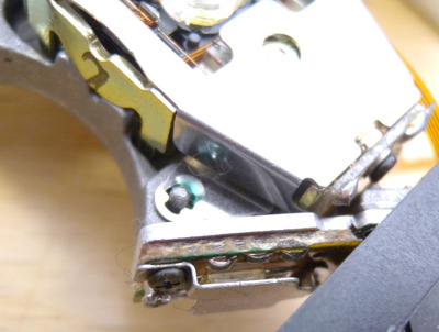
Finding a possible read head: Now that I was pretty sure the problem was with the read head, what with it having no lens, I had to figure out what could be done about it. Regluing the lens might have worked, but I didn't try that on the grounds that I have no equipment or knowledge about how to position the lens correctly. There are a couple of adjustment screws on the head, fixed with threadlock, that change the alignment of the lens assembly relative to the laser and photodiode pickup. I guess that when the head was assembled it would be put on a test jig, power applied, and someone would adjust the screws until the lens was focusing just right.
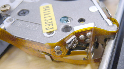
The read head had SF-92.5 stamped on it. Searching around led me to AliExpress, a place that clearly links bizarre and bazaar. There were various similarly numbered heads available (92.5, C93, C99) mostly looking very similar to the one from the CR562, but with different cables soldered to them. In particular, there are two versions, one with a 8-pin photodiode chip and one with 10-pin. The 92.5 is the 8-pin version, which gets listed as the '2 pin' type because the cable connecting to it is split as either 5+2. There were a couple with the correct cables being sold as replacements for the 3DO, but they were more than I was going to pay. The C93 though was pretty cheap, I paid around £7 for 2 (this was in 2021, I've been sitting on this for a while). It turns out it was used in some car navigation GPS sets (CDM-M2), so there must have been loads of heads available.
What if I could remove the cables from a C93, take the cables from the 92.5 and just solder them on to the C93?
That doesn't work: So I unsoldered the cables from the 92.5 with the missing lens. Which immediately threw up a problem. Some... clever?... designer had come up with a way to save a couple of suspension wires for the lens. What if the suspension wires were also the focus/tracking signal wires? You could then tension them when they get soldered to the cables and the cable would hold them in place. Genius. Of course, that does mean that unsoldering the cable causes the lens assembly to collapse, but who would ever do that? Right. That meant I couldn't just unsolder the cables from the C93. Instead I had to run some fine enameled wire (taken from a broken relay coil) from various points on the C93 to the 92.5 cables.
The end of the cable near the photodiode looked a little simpler so I had a go at fitting that in place properly. This turned out to be a bad idea. The original cable is a FFC which goes under the photodiode pins, so the pins had to be lifted. But the legs are pretty stiff, and with the heat from the iron the plastic casing shifted slightly. So I tried removing the whole chip, placing the cable and then resoldering it.
Ok, it was now time to fit the frankenstein read head. Except it didn't fit. Turns out the drive shaft on the CR562 is 3.48mm diameter on my calipers and the hole on the body of the read head is 3.1mm. Arg. Out with the drills. I was worried that 3.5mm might be too loose and my 3.4 bit drills slightly over 3.4mm, so I used that and then filed the hole slightly, managed to get a fit that was smooth without being too tight. So now I could fit it all back together. And it didn't work.
Boo. In the end that one didn't work, which may be because it was a duff head anyway, but I thought was probably me damaging or not aligning the photodiode correctly. Symptoms when it didn't work where the same as the original read head: head would try to get a focus at 3 positions on the disc (I could see the lens moving up and down at each location, with a faint red blob when looked at from the side) and then give up. So it wasn't completely wrong. Maybe.
It's also possible that by adjusting the laser power it might have worked, but the cables covered the adjusting resistor. For reference, the original (which worked) and my first attempt were both set to just under 1k ohm, the second attempt was set to 760 ohm. I think that the lower resistance leads to more power, but also that each head is different anyway, so it's not just a case of setting them all the same. I just assumed they would be set correctly as delivered.
Second attempt: I'd got two heads. So having learnt how not to do it, I had another go. Drilled the hole first. Soldered wires to the read head with dabs of silicone glue to hold things in place. This time I wired from the connector on the C93 to the photodiode bits of the cable, so no iron anywhere near anything sensitive. A bit more insulation tape and glue to hold everything in place.
Have you tried turning it off and back on again?: Finally got it all together, not looking very neat, but no cables or wires looking like they'd catch. A slight concern about how close some solder joints are to one of the carriage arms, but some insulation tape glued in place should protect that. Put it back in the computer, turned the power on, and nothing. Brief panic. Then remembered that it helps to actually plug the molex connector in.
Right. Powered on again. No disc in and I could see the head seek and try to focus, with a faint red splodge. Put an audio disc in. Wait whilst I could hear it seek. And a second later... IT SPINS UP!. YES! Boot to Windows, it shows the audio disc icon. And it plays. Put in a CDR. Reads that too. Yay!
So it's possible to replace the original SF-92.5 read head from the CR562b with an SF-C93. Given that the whole read head+ carriage assembly looks the same on the 3DO then it might work for that as well. Which might actually be of some use to somebody.
I'll edit this later with the connector pinouts. Honest.
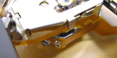
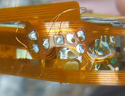
Didn't get a good photo before the second cable went on, but you can just make out the 4 wires going from the cable through the glue to the 4 pads near where the suspension/signal solder pads are.
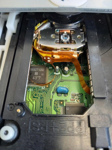
A bit easier to see the 4 wires going from the original cable, disappearing behind to the same point on the C93 cable. I removed the capacitor and variable resistor from the original cable.
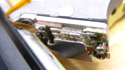
The wires for the photodiode are on the connector, then covered with a blob of silicone to provide some strain relief. I should probably have blobbed the other solder points as well given that vibration will eventually snap the fine wires.
You can see the 2-wire FFC on the right hand side, with the 5 wires on the other side. I didn't have any luck if I went anywhere near the photodiode. The most I did was to screw the original cable over the top of the metal plate.
photodiode end of cable
(numbers show which C93 connector pin goes to which solder pad on cable)
(I ran wires from the C93 connector to the cable pads and fitted the cable
over the metal photodiode cover plate)
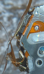
Focus/Tracking end of cable
(numbers show which C93 connector pin goes to which pin on the FFC
the goes from the connector to the 4 pads just above where the
signal/suspension wires are soldered)
(I unsoldered the short stub of FFC cable
and snipped it off to free the pads)
(resistance for 18-15 and 17-16 should both be around 8 ohms)
(care needs to be taken when soldering near the suspension wires)
(The solder MUST NOT melt or the lens will lose its suspension)
(I ran wires from the 4 pads near the suspension wires to the
pads on the cable, then glued the cable in place)
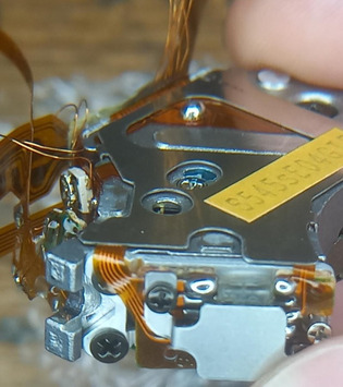
Laser section of cable
(there should be a solder blob on the C93,
remove this once everything else is done)
(Once the focus/tracking stub is removed this it's possible to get
a small iron in the solder a wire on the far side of the variable
resistor)
(I soldered to 4 wires to either side of the variable resistor and the
capacitor. The variable resistor was set to around 760 ohms)