VOGONS


First post, by The2Faces

User metadata
Rank Newbie
Rank
Newbie

Hi all,
this is here my first post, and I would like to share my experiences with a Epson Equity I, which I own, since I'm 6 years old (and I'm now quite old, end of my 3ties 😉)
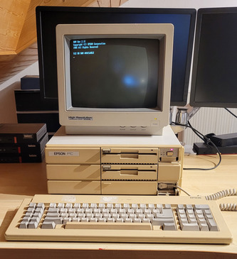
The Epson Equity I has an 8088 CPU, which "schould" be a 16Bit CPU with something around 5MHZ, which was made by NEC.
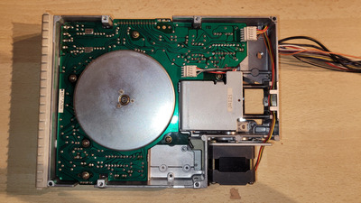
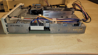
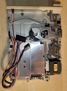
Additionaly there are two Epson 5,25" floppy drives (SD-525 ) and a 20Meg HDD with WD controller card.
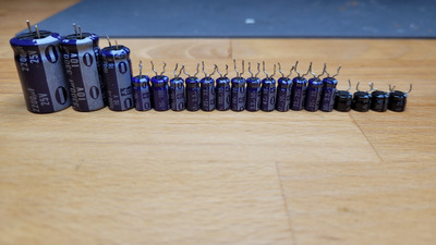
Unfortunately the floppy drives are not recognized anymore, due to whatever reasons. I checked caps (replaced already for one drive all electrolytic caps, but without success), I checked on the voltages etc, with being not too way off from the expected values (11.8V for 12V+ and 4,8-4.9V for 5V+)

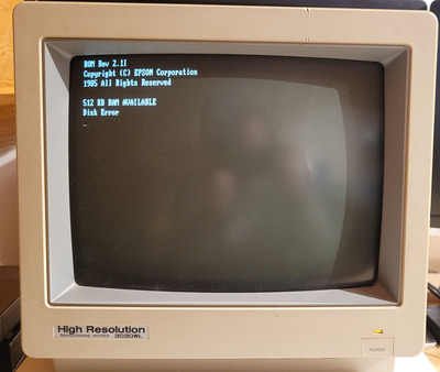
On every post the Computer responds only with the information "Disk error", which is not usual.
I remember that back in the days, when everything was working as expected, that the computer during post both drives were triggered and the heads moved. But not anymore now!
I hope somebody has an idea, what I can check from my side to get both drives up and running again. I'm little out of my options.

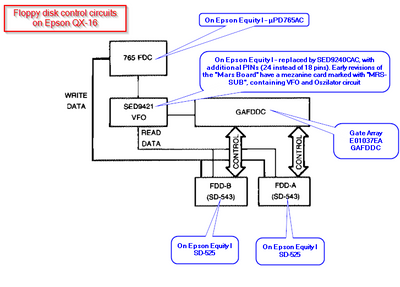
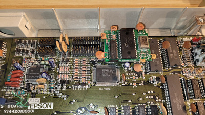
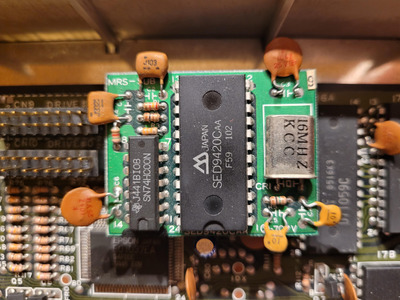
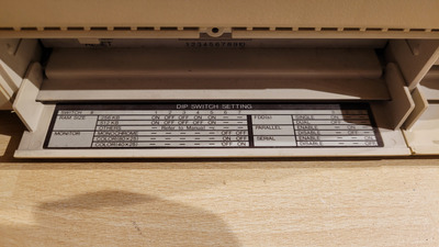
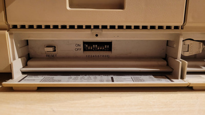
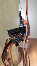
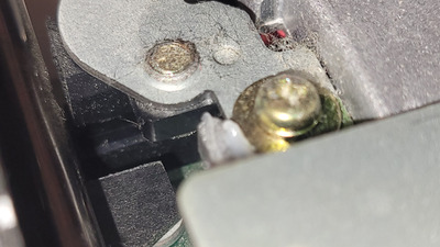
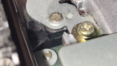
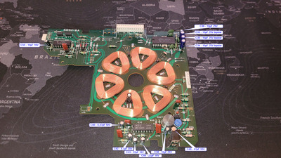
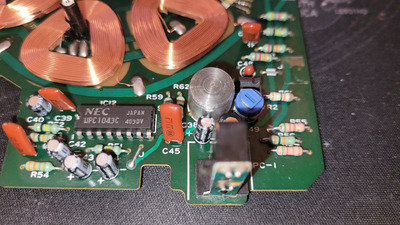
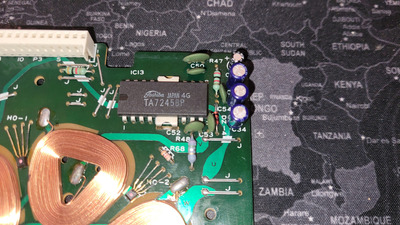
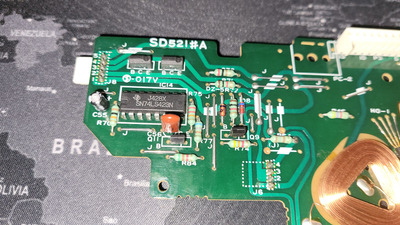
I assume, that the drives are good, but the controller may be sad. I have seen there is a daughterboard with an SED9420CAA chip, which seems to be responsible for the FDDs but I'm not sure.

Thanks!

Reply 2 of 21, by mkarcher

User metadata
Rank l33t
Rank
l33t

You are likely on the right track. The SED9420 is a part of the floppy interface. It's the more "analog like" part of the floppy interface, it's called the "data separator" and is responsible to capture the data rate of the data received from the floppy read head, so it can be processed by the floppy controller. The floppy controller chip likely has a designation like "765" in its model number, referring to the NEC µPD765, which is has been licensed and/or cloned by nearly any respectable integrated circuit company in the 80s, as it turned out to be very widespread after being used by IBM in the original IBM PC.

Re-plugging the floppy control cable and re-seating the floppy controller daughter board may be good first troubleshooting steps. If that doesn't help, a photo of the controller card might give clues how to troubleshoot it.

Be careful with your memory about the moving heads. PCs started the head moving thing when 80-track drives became used in PCs to auto-detect whether its a 40-track (360KB) or 80-track (1.2MB) drive. The classic XT with its original XT BIOS didn't know about high-capacity drives. It happens to work with 80-track 720KB drives, as they interface to the PC just like 360KB drives, though. Later BIOS versions and clones did the seek, so you might be correct about the Epson doing the seek, but depending on the computers you were exposed to, you might mix up the seek sound from a later PC with the behaviour of the Epson PC.

Reply 3 of 21, by The2Faces

User metadata
Rank Newbie
Rank
Newbie

Hi all,

I just did some work and disassembled the Epson PC completely (til I reached the Mainboard) hilarious, what you had to do back in the days to get down to the mainboard 😉.)

I will upload all pictures I made to a image hoster, due to the limitation to upload 5 pictures max for one reply.
Drives will follow.

Attachments

Reply 4 of 21, by Horun

User metadata
Rank l33t++
Rank
l33t++

Great pictures ! Have you checked the condition of the switch bank ? The Equity 1 has that switch bank from front panel,
if SW8 is not making good contact could upset the "one or two" floppy drives present or cause odd floppy issues.
Just a long shot thinking but switches on some of my old gear seem to be one source of irritation 😁
Assuming you have the manual to Equity one you know which switch am talking about...

Hate posting a reply and then have to edit it because it made no sense 😁 First computer was an IBM 3270 workstation with CGA monitor. Stuff: https://archive.org/details/@horun

Reply 5 of 21, by The2Faces

User metadata
Rank Newbie
Rank
Newbie

Yes I have a description of the dipswitch thankfully still attached to the front plate:

Thankfully I also found a english version of the Equity I manual somewhere on the web, which I just have attached to this thread.

Unfortunately I played around with the dip switches, without any changes in the behavior of the issue.
Maybe I will just use some contact spray to ensure the contact for PIN 8, but yet nothing changed for both settings (Single FFD = PIN8 ON / Dual FFD = PIN8 OFF).

Attachments

Reply 6 of 21, by The2Faces

User metadata
Rank Newbie
Rank
Newbie

So see the drive pictures attached.
On visual inspection I have more and more doubts, that the drives are the issue.
Unfortunately I can not just take another controller to hook the SD-525 floppy drives up, because of the missing shugart floppy interface, which was seemingly added later to the SD-521.

Attachments

  • 20221113_225848.jpg
    Filename
    20221113_225848.jpg
    File size
    1.86 MiB
    Views
    767 views
    File comment
    Epson Equity I - Floppy SD-525 bottom view
    File license
    CC-BY-4.0
  • 20221113_225825.jpg
    Filename
    20221113_225825.jpg
    File size
    1.26 MiB
    Views
    767 views
    File comment
    Epson Equity I - Floppy SD-525 side view
    File license
    CC-BY-4.0
  • 20221113_225807.jpg
    Filename
    20221113_225807.jpg
    File size
    1.14 MiB
    Views
    767 views
    File comment
    Epson Equity I - Floppy SD-525 connector
    File license
    CC-BY-4.0
  • 20221113_225746.jpg
    Filename
    20221113_225746.jpg
    File size
    1.06 MiB
    Views
    767 views
    File comment
    Epson Equity I - Floppy SD-525 top view
    File license
    CC-BY-4.0

Reply 7 of 21, by Horun

User metadata
Rank l33t++
Rank
l33t++
The2Faces wrote on 2022-11-14, 22:12:

Yes I have a description of the dipswitch thankfully still attached to the front plate:
Thankfully I also found a english version of the Equity I manual somewhere on the web, which I just have attached to this thread.

Great ! Have no clue how to even start to diagnose the drive issue but probably related to leaky capacitors on the controller board...
Yeah the manuals are all at https://files.support.epson.com/, to get them use Wayback machine: http://web.archive.org/web/*/https://files.su … .epson.com/pdf/*
For the Equity one type e1 in the filter box, look for e1____ps.pdf and e1____u1.pdf.
The Prod Support mentions using a different floppy controller but have never seen the one mentioned (Sysgen Omnibridge) but there are online references,
it is similar to the Joincom JC-1100 and DTK PII-151 controllers with it's own bios and support for standard and HD floppies but not the original Epson floppy drives
Back decades ago had an Equity 1 but sold it, did keep the original 3 ring hard bound manual with some orginal DOS 2.11 Epson disks.
The disk at Win world for: Microsoft MS-DOS 2.11 [Epson OEM] (5.25-360k) is about same as my Epson DOS/Setup disk. There is also a GW-Basic v2.2 disk in the book plus one other (not sure what is on it, think it DOS 2.11 supplement stuff...)
The Equity DOS manual does describe the few special Epson tools on that disk (ARCHIVE, DU, HDFMT, HDPART, HDSIT and SETUP, etc.
If I have time will take some pictures and create a PDF of those first 3 chapters...the rest of chapters is standard MS DOS 2 manual.

Attachments

  • Img_2065s.jpg
    Filename
    Img_2065s.jpg
    File size
    50.03 KiB
    Views
    754 views
    File license
    Public domain
  • Img_2066s.jpg
    Filename
    Img_2066s.jpg
    File size
    26.11 KiB
    Views
    754 views
    File license
    Public domain
  • Img_2067s.jpg
    Filename
    Img_2067s.jpg
    File size
    23.87 KiB
    Views
    754 views
    File license
    Public domain

Hate posting a reply and then have to edit it because it made no sense 😁 First computer was an IBM 3270 workstation with CGA monitor. Stuff: https://archive.org/details/@horun

Reply 8 of 21, by The2Faces

User metadata
Rank Newbie
Rank
Newbie

Hi all,

I know this thread is pretty dusty, but I rather would like to use this thread to document here the process to revive the drives.

Since the last time I posted, I had some time finally to redo all caps on the Equity I.
Unfortunately, this had little to no success, but at least, the device is not more broken than before.
It still boots with the "disk error" from bios, but the drives still do not seek during post.

I will try to create here a list, which kind of Capacitors, where put in which places on the board, but this will require some time.

Currently I plan to check on the D765AC, which is the main floppy controller (seemingly). the SED9420CAA seems only to be a data separator, whatever that might be. I have now spares from china questionable if they are legit, but maybe worth a try.

In the meanwhile I will check again on the drives, if these are may be the issue.

Attachments

  • 20240211_173224.jpg
    Filename
    20240211_173224.jpg
    File size
    973.51 KiB
    Views
    530 views
    File comment
    Replaced Panasonic Caps from the Equity from mainboard, powersupply & ISA 8 bit interface card.
    File license
    CC-BY-4.0

Reply 9 of 21, by rasz_pl

User metadata
Rank l33t
Rank
l33t

Hand laid PCB with very early Japanese SMD and THT. Gorgeous machine.

You can leave SED9420CAA alone, its responsible for reading data, not moving heads. Im pretty sure for the PC to move Head it needs to somehow detect its not over track 0. Is there a sensor in the floppy? or instead of looking for the sensor move head manually to middle position and start computer. Error might be triggered by something trivial like one of the wires connecting floppies being broken/loose. Does the documentation have diagrams? floppy pinout?

Open Source AT&T Globalyst/NCR/FIC 486-GAC-2 proprietary Cache Module reproduction

Reply 10 of 21, by The2Faces

User metadata
Rank Newbie
Rank
Newbie

I just had yesterday a look again, and yes, the drives have a light barrier to detect either track 0 or at least max. most outer position of the read/write heads.
I made for this purpose a small picture.

Light barrier open, with the sled of the heads oriented to the front of the drive:

20240224_120953.jpg
Filename
20240224_120953.jpg
File size
912.76 KiB
Views
476 views
File license
CC-BY-4.0

Light barrier closed, should represent track 0:

20240224_121010.jpg
Filename
20240224_121010.jpg
File size
951.57 KiB
Views
476 views
File license
CC-BY-4.0

I did some additional tests.
I manually moved the heads to track 0 and checked the behavior of the drives -> nothing.
When I moved the heads out of position of track 0, -> no reaction as well.

During my research I tried to find a maintenance manual on the Epson site, but unfortunately there seems to be only one for the Equity II , which differs massively from the Equity I in regards of the architecture of controlling the drives.

Maybe someone of you might have something in your Shelfs.

Reply 11 of 21, by Deunan

User metadata
Rank Oldbie
Rank
Oldbie
The2Faces wrote on 2024-02-24, 11:22:

When I moved the heads out of position of track 0, -> no reaction as well.

Most floppy drives will auto-seek to track zero on power-on. Though not all, some really old ones don't do that.
First, there is some dust there, perhaps enough have gathered in the slot of the light barrier - try blowing some air in there to clean it out. And/or you might be able to sweep it with some soft brush, if it has hair long enough some will reach into the slot.

Second, since you moved the sled and it seems to move fine - try moving it when the PC is turned on and the floppy is powered. There should be a resistance now - that is, the stepper motor should hold position and not let you move the heads easily. Don't try to overpower it, just check if it holds the sled or not. If not you might have a problem with the logic chip in the floppy drive itself. This can be dangerous to the stepper motor, sometimes this results in 12V applied to one or more of the coils and the motor will overheat in few minutes, so if you suspect that logic chip do not leave the machine turned on too long.

EDIT: Looking at the PCB I don't think this drive even has a logic chip on it, seems like the PCB is only populated with motor coil driver chips and all the logic is handled by the PC. Is it possible to unscrew and make a photo of the upper side? That at least would tell you if the stepper chip is just a dumb driver or does it do timing and sequencing on its own, and takes direction and step signals from the PC. In the latter case it might be possible to test it with some jig (power supply and some buttons).

Reply 12 of 21, by The2Faces

User metadata
Rank Newbie
Rank
Newbie

I recapped both drives now, without any change of behavior.
Also I did some additional testing on MS Dos level. Seems like, that the controller does not see in any way the drive.
Interestingly I'm able to trigger the drive, that the LED jumps on and the drive spins, but no reaction of the stepper motor for the heads.
If there is any resistance on the stepper motor, when the drive tries to access the disk, I have not yet tried.

For documentation purposes I made markings of the replaced caps and their original value. (only the bipolar C33 to C35 ar original)

2024-02-25 12_36_44-20240225_113436.jpg
Filename
2024-02-25 12_36_44-20240225_113436.jpg
File size
1.44 MiB
Views
437 views
File license
CC-BY-4.0

Lower part of the SD521A with motorcontrol IC

20240225_113452.jpg
Filename
20240225_113452.jpg
File size
1.93 MiB
Views
437 views
File license
CC-BY-4.0

Upper right part of the SD521A with motordriver IC and bipolar caps (blue)

20240225_113459.jpg
Filename
20240225_113459.jpg
File size
1.71 MiB
Views
437 views
File license
CC-BY-4.0

Upper left part of the SD521A with TTL monostable multivibrator IC

20240225_113506.jpg
Filename
20240225_113506.jpg
File size
1.79 MiB
Views
437 views
File license
CC-BY-4.0

So overall there is not interface control circuit on the floppy drive, like on drives with an additional on top pcb with e.g. a Shugart interface.
This seems to be on mainboard of the Epson Equity I.
My research on that was, that either the GAFDDC / E01037EA of Epson (see pictures above) or the Hitachi HA16642MP have an issue.

By the way I replace the SED9420C with another chip, resulting in no post. Seems like I was delivered either a faulty or fake chip. Also same situation is, if the additional MRS-SUB board with the SED9420Caa chip is not present, the Equtiy does not post.

I tested also the FDD main controller µPD765A on the Equity by replacing it with another chip of the same kind, without any changes.

Reply 13 of 21, by Deunan

User metadata
Rank Oldbie
Rank
Oldbie
The2Faces wrote on 2024-02-25, 12:20:

If there is any resistance on the stepper motor, when the drive tries to access the disk, I have not yet tried.

No need to wait for disk access, the sled should become "stiff" when system is powered on.

The2Faces wrote on 2024-02-25, 12:20:

So overall there is not interface control circuit on the floppy drive, like on drives with an additional on top pcb with e.g. a Shugart interface.

With the photos of the other side of the PCB it's now possible to figure out the circuit, and I have to say I'm a bit surprised it's a double-sided PCB but still has no hole plating and there are still jumper wires used.
Anyway, the 74LS423 is just a '123 except with minor improvements to how it works. That's a timing chip and I belive it's only purpose is to limit the current through the stepper motor windings when there's no head movement. The actual stepper phases are generated not by this PCB but the main board.

So first check the sled when system is powered, if it's "limp" and you can move it as easily as when not powered it would suggest either a complete failure of the stepper driver chip, or perhaps those two transisors above 74LS423 are blown.
The motor windings are connected directly to the big white connector, looks like pins 9-12, see where that goes on the main PCB. I would expect some driver chip, maybe even good old ULN200x series, to be there. The 765 FDC only has 2 outputs, /DIRC (direction) and /STEP - so there must be some logic that translates that into stepper motor coil phases, and a driver (that could be one custom chip for both).

You can check if the 765 generates stepping pulses, if you don't have a scope then an LED with 1k resistor will do. Steps are at least 3ms long and the pulses should cause the LED to blink. Make sure to move the sled out of track 0 sensor range for this.

Reply 14 of 21, by The2Faces

User metadata
Rank Newbie
Rank
Newbie

Thanks for your input. It tested the sled -> total limp. No activation of the stepper motor in any situation.

I poked little bit more in the internet, and found a service manual for the successor of my model (Equity II). There are the SD-521 drives also built in, which are nearly the same, with the difference, that each drive has its own control circuit (top-board), which the SD-525 not have (only the mentioned motor control board / bottom part of the drive).
Thankfully there was a schematic inside 😁. You were nearly wright.
Instead of the pins 9 - 12 it is 10 - 13, which go from the stepper motor to the main board.

To ease up the diagnostics, I have put the the pin-out of the P3 (white connector) together:
SD-525 motorboard (marked as SD-521A) pin-out for P3:

Pin 1 : +12V
Pin 2 : GND
Pin 3 : Write Protect lightbarrier
Pin 4 : NOT MOTOR START
Pin 5 : +5V
Pin 6 : NOT STEP MOTOR POW UP
Pin 7 : Track 0 detection lightbarrier
Pin 8 : NOT HEAD LOAD (not used)
Pin 9 : Drive select
Pin 10: Step motor pin 4
Pin 11: Step motor pin 2
Pin 12: Step motor pin 3
Pin 13: Step motor pin 1
Pin 14: Head Cont (not used)

Filename
Epson-SD-521&SD-525_Motor_control_board.pdf
File size
1.72 MiB
Downloads
12 downloads
File license
CC-BY-4.0

I think I will follow up and check the mainboard again.
Unfortunately it is really a challenge to get into this, when having the mainboard covered by the PSU and the upper chassis.
Maybe I will just use an external ATX-PSU to power that thing.

I will update you as soon as I have solved the issue with the covered board for probing.

Reply 15 of 21, by Deunan

User metadata
Rank Oldbie
Rank
Oldbie
The2Faces wrote on 2024-02-25, 19:42:

I will update you as soon as I have solved the issue with the covered board for probing.

See if pin 5 of the stepper motor connector (on the drive PCB) is at 5V. This should be its default level and this voltage should raise to 12V when stepping. If you can't easily access that point then solder or clip a wire to it for testing purposes.

If 5V is there and the sled is limp it's either the failure of the driver for all 4 phases (dead chip or has power delivery issues) or possibly the motor itself was overheated before. Test all the coils in the motor, there should be an equal resistance from pin 5 to pins 1-4 on the connector. What the driver chip does is provide a ground to one (or two if half-stepping) phases. If all of the pins 1-4 float at the same voltage as pin 5 then you pretty much nailed the problem to the driver chip.

If there is no voltage at pin 5 it might be a damaged transistor or a broken connection somewhere on the drive PCB. It's unlikely but not impossible - and frankly would be easier to fix so I don't expect such luck.

Reply 16 of 21, by The2Faces

User metadata
Rank Newbie
Rank
Newbie

I have checked the voltage on Pin5, which is 5V and keeps 5V and nothing bejond.
The coils are all for the steppermotor are all between 146 - 150 ohm, which seem to look fine.
I replaced the 74LS423N on one drive, with a known working chip just with the same result, that the BIOS reports DISK Error.

I do not think that the drives (both) are the problem. Currently I try to figure out, why the BIOS detects there the drive error.
I just dumped for that the current BIOS with revision 2.1I, which is the second release, of four.

See here the list of the available ROMs:

Filename
Epson_Equity_I_BiosRom_V2_1I.zip
File size
6.5 KiB
Downloads
10 downloads
File license
CC-BY-4.0

Reply 17 of 21, by Deunan

User metadata
Rank Oldbie
Rank
Oldbie
The2Faces wrote on 2024-02-29, 23:15:

I do not think that the drives (both) are the problem. Currently I try to figure out, why the BIOS detects there the drive error.

I think so too. 5V being present and the coils not open, the stepper should be holding the sled in place. It's not because none of the pins 1-4 are getting grounded by the mobo.
BIOS might have a floppy seek function and it simply times out trying to step the head out of track 0 position and back.

The2Faces wrote on 2024-02-29, 23:15:

I just dumped for that the current BIOS with revision 2.1I, which is the second release, of four.

I find it curious that two of four BIOS releases had some fixes to floppy drive handling. But then again this mobo uses non-standard floppy drives with most of the logic and signal processing being on the mainboard instead.
Looking at your mobo photos again, I don't see any typical coil drivers but there's a bunch of of transistors there, near floppy connectors. It's rather unlikely that all of them got blown so I wonder if there is a fusible resistor somewhere, or a broken connection?
I'm pretty sure the chip responsible for the stepper phasing is the Epson GAFDDC - that's a gate array chip, a PLD of sort except factory-programmed, I couldn't find any datasheet for it. Some of these early gate arrays can just die, and they do tend to get rather warm during operation. I spy a test point nearby marked STP - could be step signal from the D765A, if you have a scope it would be worth checking if any pulses show up there. Or on the D765A output.

Reply 18 of 21, by The2Faces

User metadata
Rank Newbie
Rank
Newbie

Thanks again for your Input.

I had the same thoughts about the GAFDDC and I really really hope that this chip is not toast. Just for the reason, that it is nearly impossible to source it new to replace with an FPGA without the help of EPSON.
Regarding this chip I made also some additional research, which led me to a service manual of the Epson QX-16 PC, which was kind of a wierd mix of Zilog and 8088 chips.
But the most important part lies within the service manual, which explains, how the GAFDDC works, together with slightly different drives (SD-543 instead of SD-525).

To give you here an example, this block overview helps a lot to understand, how the whole setup was done by Epson back in the days.

Espon Equity I - Blockshemata Floppy Control Circuit.png
Filename
Espon Equity I - Blockshemata Floppy Control Circuit.png
File size
49.98 KiB
Views
294 views
File license
CC-BY-4.0

Here is the interesting part for the floppy drives I pulled from the 174 pages service manual:

Filename
Epson-QX-16_Floppy_Controller.pdf
File size
4.89 MiB
Downloads
12 downloads
File license
CC-BY-4.0

I will check the 16Mhz crystal for the value, but currently I have issues to find my damn oscilloscope.

Let's see tomorrow, what I will find out.

Reply 19 of 21, by rasz_pl

User metadata
Rank l33t
Rank
l33t
The2Faces wrote on 2024-03-02, 00:06:

I had the same thoughts about the GAFDDC and I really really hope that this chip is not toast. Just for the reason, that it is nearly impossible to source it new to replace with an FPGA without the help of EPSON.

worst case scenario you could desolder everything behind D765 and graft in guts from another floppy pcb to handle stepper motors.
As deunan said measuring pins 33 35 37 of D765A is a good start. pins 69-77 of GAFDDC will also be interesting, and 68 TK0 and 2? for TK1.

Open Source AT&T Globalyst/NCR/FIC 486-GAC-2 proprietary Cache Module reproduction