Reply 1160 of 1184, by Sphere478

- Rank
- l33t++
feipoa wrote on 2024-03-29, 09:50:I also experimented with some parallel resistors. No judgements please! I didn't want to put a whole lot of time into this. I […]
I also experimented with some parallel resistors. No judgements please! I didn't want to put a whole lot of time into this. I don't have a large enough stockpile of power resistors in the 0-15 ohm range. The largest resistors I had in this range were 2 W, so I placed them in parallel to share in heat dissipation:
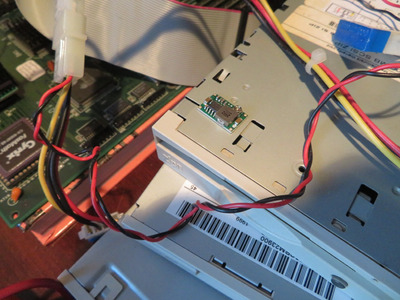
SXL2-90_17.JPGI ultimately landed with this. It is 5.1-ohm, 5.1-ohm, 10-ohm:
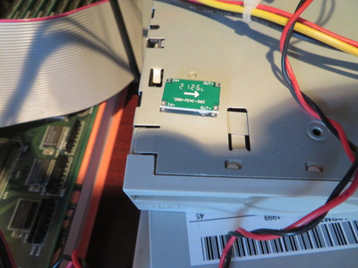
SXL2-90_18.JPG
The parallel resistance was 2.0-ohms. Vin was 11.6 V, and the combination initially dropped the voltage by 2.1 V, but as time went on, deltaV increased to 2.5 V and reached 63 C after about 8 minutes. I am guessing that the resistance of the resistors is increasing as they heat up. From these values, we can see that the incoming current is 2.1 V / 2ohm = 1.05 A. Without the resistor, I guess we have to take the word of the DMM, which measured 2 A, but when the DMM leads are connected, the system won't POST - just black screen.EDIT: Well this is embarrassing. I forgot to move the DMM's lead to the current terminal. Now that I've corrected the leads, I am getting 0.95 A while sitting at the DOS prompt. This measurement is without the parallel resistor pack. So, roughly 6.1 Watts to dissipate as heat ((11.6-5.15)/0.95)?
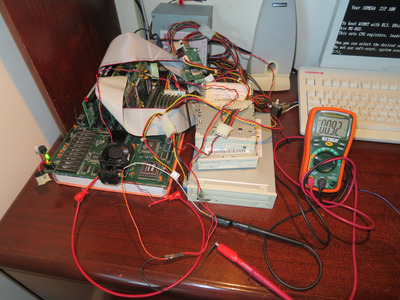
In action:
SXL2-90_19.JPGRunning Win3.11:
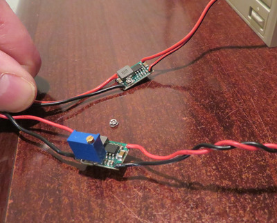
SXL2-90_20.JPGMy other set of finger wound paraelle resisitors also had a drop of 2.5 V as shown on the DMM here:
SXL2-90_21.JPGI decided that I didn't want a single point of that much heat in the case without active dissipation (a fan). it was easier for me to cool the VRM with a fan. Also, I would have needed to paste on some silicone to insulate those leads. It is too easy to short it out on some metal in the case. Alternately, I might order some 10-20 W resistors on my next digikey order. I was thinking of this 2.2 ohm beast: https://www.digikey.ca/en/products/detail/yag … AJB-2R2/9167212
I haven't had any crashes with the SXL2 at 90 MHz. I will be setting up w95 and NT4 on a seperate CF card, so this will provide more insight concerning stability.
No judgments, that’s how experiments are done! 😀
I think you should give a murata buck converter a try look in my sig, pcb projects, top of first post.