VOGONS


First post, by AppleSauce

User metadata
Rank Oldbie
Rank
Oldbie

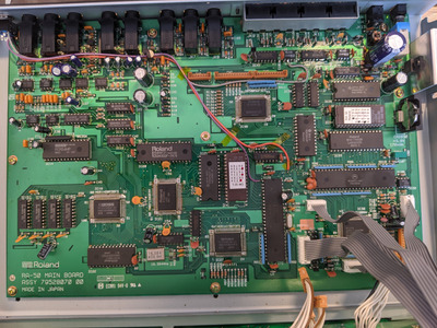
So the story goes like this : my friend picked up a Roland RA-50 and we've been thinking about modding it .
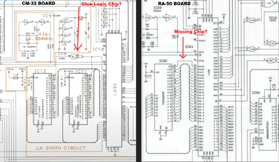
In theory would it be possible to "upgrade" it to a CM32L by adding in the PCM rom?

Or am I barking up the wrong tree?

Looking at the schematics it seems like the extra PCM chip is just piggybacked to the original pcm rom
and then both roms are linked to a glue logic chip which is then in turn linked to a pin on the LA synthesizer.

Its probably more complicated than that but I figured what the heck might as well ask.

Roland2.png
Filename
Roland2.png
File size
1.42 MiB
Views
705 views
File license
Public domain

Reply 2 of 13, by AppleSauce

User metadata
Rank Oldbie
Rank
Oldbie
pentiumspeed wrote on 2021-09-13, 23:21:

74HC02 TTL CMOS logic IC obtainable anywhere.

Cheers,

Ah good to know its easily obtainable ,
Still I don't know how involved adding the extra CM32L PCM ROM chip would be ,
I think you can have two roms linked together right?
Some bios are split into 2 chips and whatnot?

So like has anyone tried doing this to their RA-50?

Reply 3 of 13, by snufkin

User metadata
Rank Oldbie
Rank
Oldbie

I may have had too much beer, but it might be possible to piggy back the ROMs on top of each other, but lift pin 22 (!CE) on the top one, and connect it via an inverter (something like this: https://www.farnell.com/datasheets/158131.pdf ) with an input from pin 22 on the lower one. Pretty sure that's what the circuit diagram you posted at the start is doing (inverting inputs of an AND gate tied together makes it work like a NOT gate), making the RA19 output from the LA32 (pin 59) act as a select switch between the two ROMs.

But I've never tried doing this, so it might be a bad idea.

Reply 5 of 13, by Tiido

User metadata
Rank l33t
Rank
l33t

You also need the CPU program ROM of CM32L to actually have the extra sounds usable, the ROM already there will not know anything about the extra sounds.

You can also use a 27C801 or some other 1MByte EPROM and a wire from A19 to the EPROM A19 to get the full sample set without needing to split stuff up between existing and newly added ROM.

T-04YBSC, a new YMF71x based sound card & Official VOGONS thread about it
Newly made 4MB 60ns 30pin SIMMs ~
mida sa loed ? nagunii aru ei saa 😜

Reply 6 of 13, by RichB93

User metadata
Rank Member
Rank
Member

Ah 0kay- I assumed it was the same CM32L ROM already in the RA-50 as it is labelled as such.

I'm still a bit lost as to what needs to be done (electronics isn't my strong suit!)

Replace CM-32L ROM on board with 'actual' CM-32L ROM
Flash CM-32L PCM ROM onto 27C801 chip.
Piggyback burned PCM ROM chip on top of TC534000P-7476 chip, lifting pin A19 and connect this to pin 59 of the LA32 chip?

EflAJZDU0AAh0Fg.jpeg
Filename
EflAJZDU0AAh0Fg.jpeg
File size
1.92 MiB
Views
242 views
File license
Fair use/fair dealing exception

I attach a picture of the RA-50 board as I can update it as I can annotate it for others once we figure it out 😀

EDIT: I'm an idiot and just saw snufkin's comment above *facepalm*. So you'd also need an 74HC02 to invert A19 so it's not selected at the same time as the original ROM?

Reply 7 of 13, by Tiido

User metadata
Rank l33t
Rank
l33t

You need the inverter chip only if you are going to use two 512KB EPROMs. In that case original A19 goes into !CE line of original (as it does already) and inverted A19 goes into !CE of the new ROM, all other pins are parallel. All other unused sections of the inverter chip have to have all the inputs signals connected to something, they cannot remain floating except maybe if you use a TTL and not CMOS type part but even then, it is always polite to connect any unused inputs to something (nearby GND, VCC, output of another section etc.).

In case of using single 1MByte EPROM you remove the original sample ROM entirely, put in the new one and connect A19 straight to A19 of the EPROM, while !CE line gets separated from A19 line and connected to ground. I personally would go with this option, since it can be done cleaner.

I have actually missed there was a CM32L program ROM in the machine already, in that case you don't need to do anything more about the program ROM.

T-04YBSC, a new YMF71x based sound card & Official VOGONS thread about it
Newly made 4MB 60ns 30pin SIMMs ~
mida sa loed ? nagunii aru ei saa 😜

Reply 8 of 13, by RichB93

User metadata
Rank Member
Rank
Member

Ah, that makes more sense! Thank you for the explanation.

I agree that it'd be much nicer to remove the ROM and install a socket + UVEPROM + A19 mod, although I'd need to invest in a good vacuum desoldering gun to do so.

Reply 9 of 13, by RichB93

User metadata
Rank Member
Rank
Member

So, I gave this a go using the piggybacked chip method, but sadly to no success.

Got a M27C4001 PROM and burned the upper half of the CM32L PCM ROM to it.

Got a SN74HC02N and wired it as follows:

74x02.png
Filename
74x02.png
File size
30.97 KiB
Views
131 views
File license
Fair use/fair dealing exception

Pin 2 of the SN74HC02N was soldered to the CE line on the original ROM, and pin 1 to the CE pin on the new ROM.

Powered on and no magic smoke. Tested standard LA voices and they were OK.

Tested channel 10 and played the upper notes, which I believe is where the extra CM32L sound effects notes are located. But no sound.

Any ideas? Have I made any schoolboy errors? I assume that pulling pin 3 to low was correct, as otherwise I'd probably get voice corruption if pulling it high and it being active as the same time as the original chip.

Admittedly the chip was piggybacked without soldering, but all pins had a connection.

Maybe there's another connection needed somewhere to 'tell' the operating ROM that both PCM ROMs are present?

Reply 11 of 13, by RichB93

User metadata
Rank Member
Rank
Member

So I committed to it and soldered the chip in place, just in case there were bad connections.

Unfortunately it seems that it still isn’t working. Comparing to Phil’s computer lab video on the MT32 and CM32, I’m still getting the MT32 sound effects for beneath a steel sky.

Not sure what’s next for this project really! I may leave it as is.

Reply 12 of 13, by RichB93

User metadata
Rank Member
Rank
Member

I’ve been poring over the data sheets and I think I’ve spotted my mistake. I’ve not connected VPP, as I assumed that it was only required for programming and not when in use… unfortunately I removed the leg, thinking it wouldn’t be needed!

I’ve just ordered a dremel to grind away some of the chip and I’ll connect it to VCC.

Reply 13 of 13, by Tiido

User metadata
Rank l33t
Rank
l33t

The logic as you connected it should work, and the VPP pin shouldn't really matter although the datasheets do tell it to connect to a specific state for normal operation and I suppose some EPROMs do need it not to float.

Game doesn't know what it is connected to so it think it needs to be specifically told that. I would think it is strange if a game uses features that aren't guaranteed to be present...
(unless there are identification commands that the MIDI device returns via its MIDI OUT that the game can listen to ? In such a case you need to mod the MIDI OUT signal path on the device also not just MIDI IN)

T-04YBSC, a new YMF71x based sound card & Official VOGONS thread about it
Newly made 4MB 60ns 30pin SIMMs ~
mida sa loed ? nagunii aru ei saa 😜