VOGONS


Problem with PSU adapter

Topic actions

Reply 20 of 42, by momaka

User metadata
Rank Member
Rank
Member
boby wrote on 2024-04-08, 17:42:

My current adapter is also straight-through.

Ah, OK, that's probably why it's not working then.
I though this whole time your adapter was a special one for converting these proprietary PSUs.

boby wrote on 2024-04-08, 17:42:

So I guess, this Pin 11 is the problem, because it is not connected

According to one of your posts above,
"11: Rose 3VAUX"

3VAUX (3.3VSB) has no place on a standard ATX pinout. Only the 5VAUX (5VSB) does. So it's fine that pin 11 is not connected. Do NOT connect it to anything.

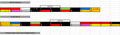
Again, if the pinout you posted several posts ago above is correct, then this is how it should be wired:

PIN # ON COMPAQ PSU ---------> PIN # on -standard- ATX connector
1: Brown 3V -------------------> pin #1
2: Brown 3V ------------------> pin #2
3: Black GND -----------------> pin #3
4: Red 5V --------------------> pin #4
5: Black GND -----------------> pin #5
6: Red 5V --------------------> pin #6
7: Gray ? ---------------------> pin #8 (??) (equivalent to PWR_OK??)
8: Thin Purple FAN_ON --------> leave disconnected for now
9: Green 5V AUX --------------> pin #9
10: Orange +12V --------------> pin #10
11: Rose 3VAUX ----------------> do NOT use / leave disconnected
12: Thin Red-White FAN-CMD ---> leave disconnected for now
13: Brown 3V ------------------> pin #11
14: Blue: -12V -----------------> pin #12
15: Black GND -----------------> pin #13
16: Thin White ON-STBY --------> pin #14 (equivalent to PS_ON??)
17: Black GND -----------------> pin #15
18: Black GND -----------------> pin #16
19: Black GND -----------------> pin #17
20: Thin Yellow ? ---------------> leave disconnected (this pin is reserved the -5V rail)
21: Red 5V ---------------------> pin #19
22: Red 5V ---------------------> pin #20
23: Thin Brown 3VRS -------------> bridge with either pin #1, 2, or 3 (3.3V rail sense pin??)
24: Thin Blue-White FAN_SINK ----> leave disconnected for now

With this, note that we didn't use pins 8, 11, 12, 20, and 24 from the Compaq PSU.
#11 we don't use.
#8, 12, and 24 might be signal pins for the Compaq PSU's fan, so not sure what to connect to at the moment, but they might need to be connected to something.
That leaves only #20, which I'm not sure what it is used for. You'll need to trace where it goes inside the PSU. Might be another signal or voltage sense pin... which again, may be needed for the PSU to sustain PS_ON.

Reply 21 of 42, by boby

User metadata
Rank Member
Rank
Member

Should be correct, as those are the labels I found inside of PSU. Can't trace pin 20, as this yellow cable is thight with other cables and there is some glue on top of that so can't see what is written there.
I will try without it first with the mods you wrote

Thx a lot! Going to try now

Reply 22 of 42, by boby

User metadata
Rank Member
Rank
Member

Ok, so I did everything you suggested and it is still the same, but there is a progress 😀
This time, when I power on the PC, CPU FAN spins for a bit longer and even PSU FAN starts spinning and then all turns off again, after, let's say 1.5 seconds.

Reply 23 of 42, by ODwilly

User metadata
Rank l33t
Rank
l33t

If the hole for the PSU that works with it is to large you can get a piece of flat metal and just drill some holes to make an adapter. I had to do that with a XW4600 HP workstation

Main pc: Asus ROG 17. R9 5900HX, RTX 3070m, 16gb ddr4 3200, 1tb NVME.
Retro PC: Soyo P4S Dragon, 3gb ddr 266, 120gb Maxtor, Geforce Fx 5950 Ultra, SB Live! 5.1

Reply 24 of 42, by boby

User metadata
Rank Member
Rank
Member
ODwilly wrote on 2024-04-08, 21:20:

If the hole for the PSU that works with it is to large you can get a piece of flat metal and just drill some holes to make an adapter. I had to do that with a XW4600 HP workstation

They are to small. Compaq PSU is larger. So even if I mount it somehow (holes do not match), there would be an empty space on the back and it would look ugly.

Reply 25 of 42, by boby

User metadata
Rank Member
Rank
Member

My friend has a working compaq adapter from 20 pins to 24 pins (vise-verse that I need), so it might be helpful:

Attachments

Reply 26 of 42, by momaka

User metadata
Rank Member
Rank
Member
boby wrote on 2024-04-08, 19:20:

Should be correct, as those are the labels I found inside of PSU. Can't trace pin 20, as this yellow cable is thight with other cables and there is some glue on top of that so can't see what is written there.

If it's not too difficult, could you try removing the glue? Or is it in an area with lots of tall components (probably capacitors) around it that you can't get to it? If so, don't worry. But if possible, it might be helpful to know.

boby wrote on 2024-04-08, 20:00:

Ok, so I did everything you suggested and it is still the same, but there is a progress 😀
This time, when I power on the PC, CPU FAN spins for a bit longer and even PSU FAN starts spinning and then all turns off again, after, let's say 1.5 seconds.

Good, hopefully we can do another test now with this (I'll detail it a little further below.)

boby wrote on 2024-04-09, 09:25:

My friend has a working compaq adapter from 20 pins to 24 pins (vise-verse that I need), so it might be helpful:

Interesting. It appears that adapter is pretty much wiring pins straight-through without any modification... which is probably OK, since it converts a regular ATX PSU to just push out the needed voltages to the Compaq motherboard, and regular ATX PSUs don't have any other signal input wires, apart from PS_ON. PG (Power Good or Power OK) is only for the motherboard to know that the PSU is up and ready with the voltages.

In contrast, (again) I suspect the issue is with the Compaq PSU is that it is expecting a few more signals back from the motherboard, which the Compaq board does... and it's probably from pins 8, 12, 20, and 24.

So let's do the following test:
1) Plug PSU into the wall but leave it unplugged from the motherboard. Do not plug in the adapter. However, do plug in a few fans and a (non-critical) HDD or two on the molex connectors (for the fans, put a few on the 12V rail and a few on the 5V rail so that there is a load on each.)
2) Put a wire bridge between pins "23: Thin Brown 3VRS" and "1: Brown 3V". Make sure the connection is secure. This is the 3.3V sense return, so the PSU can sense it's outputting 3.3V properly.
3) Take your multimeter and hook the black probe to ground/COM (into a black wire on one of the molex connectors would be best.)
4) Set multimeter to DC voltage (20V DC range if using a manual-ranging one) and measure the voltage for the following pins below
-- a) pin "7: Gray"
-- b) pin "8: Thin Purple FAN_ON"
-- c) pin "12: Thin Red-White FAN-CMD"
-- d) pin "16: Thin White ON-STBY"
-- e) pin "20: Thin Yellow ?"
-- f) pin "24: Thin Blue-White FAN_SINK"
5) report numbers from step #4 above in your next post as "Voltages, PSU in Soft-Off state"
6) Put a wire bridge between pin "16: Thin White ON-STBY" and any of the ground/COM pins to turn On the PSU and repeat the same voltage measurements as in step #4 again. If the PSU turns Off before you're able to measure the voltage on a pin, remove wire bridge between pin 16 and ground, then bridge again to turn On the PSU again. You'll probably need to do this for each measurement, since the PSU will likely turn off.
7) Once you get the all of the voltage measurements from step #6 above, report in your post as "Voltages, PSU in On state"

By doing this test, hopefully we can see how the voltage on each of these pins change (if at all.)

More than likely, we might have to either bridge or pull up/down the pins for FAN_ON, FAN_SINK... and who knows about the thin yellow one (probably will be safest to use a resistor to pull up/down that one... but we'll get to that after the test results.)

Reply 27 of 42, by boby

User metadata
Rank Member
Rank
Member

Not possible to remove the glue. I would need first to unsolder few wires from below in order to even try to remove it. It is very narrow space and the glue is all around wire including some components too.
Will try your test, but I don't have any fans, so I will connect HDD, CD Drive & Floppy

Reply 28 of 42, by boby

User metadata
Rank Member
Rank
Member
momaka wrote on 2024-04-10, 13:38:
If it's not too difficult, could you try removing the glue? Or is it in an area with lots of tall components (probably capacitor […]
Show full quote
boby wrote on 2024-04-08, 19:20:

Should be correct, as those are the labels I found inside of PSU. Can't trace pin 20, as this yellow cable is thight with other cables and there is some glue on top of that so can't see what is written there.

If it's not too difficult, could you try removing the glue? Or is it in an area with lots of tall components (probably capacitors) around it that you can't get to it? If so, don't worry. But if possible, it might be helpful to know.

boby wrote on 2024-04-08, 20:00:

Ok, so I did everything you suggested and it is still the same, but there is a progress 😀
This time, when I power on the PC, CPU FAN spins for a bit longer and even PSU FAN starts spinning and then all turns off again, after, let's say 1.5 seconds.

Good, hopefully we can do another test now with this (I'll detail it a little further below.)

boby wrote on 2024-04-09, 09:25:

My friend has a working compaq adapter from 20 pins to 24 pins (vise-verse that I need), so it might be helpful:

Interesting. It appears that adapter is pretty much wiring pins straight-through without any modification... which is probably OK, since it converts a regular ATX PSU to just push out the needed voltages to the Compaq motherboard, and regular ATX PSUs don't have any other signal input wires, apart from PS_ON. PG (Power Good or Power OK) is only for the motherboard to know that the PSU is up and ready with the voltages.

In contrast, (again) I suspect the issue is with the Compaq PSU is that it is expecting a few more signals back from the motherboard, which the Compaq board does... and it's probably from pins 8, 12, 20, and 24.

So let's do the following test:
1) Plug PSU into the wall but leave it unplugged from the motherboard. Do not plug in the adapter. However, do plug in a few fans and a (non-critical) HDD or two on the molex connectors (for the fans, put a few on the 12V rail and a few on the 5V rail so that there is a load on each.)
2) Put a wire bridge between pins "23: Thin Brown 3VRS" and "1: Brown 3V". Make sure the connection is secure. This is the 3.3V sense return, so the PSU can sense it's outputting 3.3V properly.
3) Take your multimeter and hook the black probe to ground/COM (into a black wire on one of the molex connectors would be best.)
4) Set multimeter to DC voltage (20V DC range if using a manual-ranging one) and measure the voltage for the following pins below
-- a) pin "7: Gray"
-- b) pin "8: Thin Purple FAN_ON"
-- c) pin "12: Thin Red-White FAN-CMD"
-- d) pin "16: Thin White ON-STBY"
-- e) pin "20: Thin Yellow ?"
-- f) pin "24: Thin Blue-White FAN_SINK"
5) report numbers from step #4 above in your next post as "Voltages, PSU in Soft-Off state"
6) Put a wire bridge between pin "16: Thin White ON-STBY" and any of the ground/COM pins to turn On the PSU and repeat the same voltage measurements as in step #4 again. If the PSU turns Off before you're able to measure the voltage on a pin, remove wire bridge between pin 16 and ground, then bridge again to turn On the PSU again. You'll probably need to do this for each measurement, since the PSU will likely turn off.
7) Once you get the all of the voltage measurements from step #6 above, report in your post as "Voltages, PSU in On state"

By doing this test, hopefully we can see how the voltage on each of these pins change (if at all.)

More than likely, we might have to either bridge or pull up/down the pins for FAN_ON, FAN_SINK... and who knows about the thin yellow one (probably will be safest to use a resistor to pull up/down that one... but we'll get to that after the test results.)

Voltages, PSU in Soft-Off state:
7 ----> 0.02V
8 ----> 0V
12 ----> 0V
16 ----> 0V
20 ----> 0V
24 ----> 0V

Voltages, PSU in On state -> it didn't turn on 😒

Update1:

momaka wrote on 2024-04-10, 13:38:

6) Put a wire bridge between pin "16: Thin White ON-STBY" and any of the ground/COM pins to turn On the PSU and repeat the same voltage measurements as in step #4 again. If the PSU turns Off before you're able to measure the voltage on a pin, remove wire bridge between pin 16 and ground, then bridge again to turn On the PSU again. You'll probably need to do this for each measurement, since the PSU will likely turn off.

While trying to turn the PSU on (step 6), so I still need to keep bridge from step 2? I did it without that bridge, is that why it is not turning on?

Reply 29 of 42, by momaka

User metadata
Rank Member
Rank
Member
boby wrote on 2024-04-10, 17:15:

While trying to turn the PSU on (step 6), so I still need to keep bridge from step 2? I did it without that bridge, is that why it is not turning on?

Yes, always keep bridge from step 2 (between 3VRS to one of the brown 3V rails)

Also, you didn't get any voltage for item d) from step 4)??
I expect "16: Thin White ON-STBY" to show upwards of 3.3V up to 5V - basically the same as the PS_ON signal from a regular ATX PSU. Check your measurements again. If you still get no voltage for that one, what voltage do you get on "9: Green 5V AUX"? That one should definitely be 5V. If not, re-check your measurements and multimeter.

Reply 30 of 42, by boby

User metadata
Rank Member
Rank
Member
momaka wrote on 2024-04-14, 00:11:

Also, you didn't get any voltage for item d) from step 4)??

No, no voltage on it after bridging pin 23 & pin 1 nor after bridge of pin 16 & ground pin
At this point only pin 9 has 5V and pin 11 has 3.3V

Update1:
Nothing changed after both bridge (pin 23 + pin 1 and pin 16 with ground pin).
Everything is 0V except of pin 9 which is 5V and pin 11 which is 3,3V - regardless of bridge. There is always voltage on those two in soft off mode.

Update2:
Can I bridge pin 23 & pin 1 while connected to the board and try to turn it on using the board switch?

Update3: thin yellow wire, pin 20 seams to be -5V
I removed some glue, but I belive it is that.

Reply 31 of 42, by boby

User metadata
Rank Member
Rank
Member

After a lot of thinking I came to conclusion that this PSU actually do match standard ATX version 100%
The only difference are those 4 extra wires, which causes PSU not to start for some reason...not sure what and why

Reply 33 of 42, by momaka

User metadata
Rank Member
Rank
Member
boby wrote on 2024-04-14, 08:54:

No, no voltage on it after bridging pin 23 & pin 1 nor after bridge of pin 16 & ground pin
At this point only pin 9 has 5V and pin 11 has 3.3V

Hmmm.. that's not quite right.
ATX PSUs have two voltages when in soft-off mode: 5VSB (measuring at 5V +/-5%) and PS_ON (typically close to 5V, but can range anywhere down to 3V.)
I don't see any of the pins in question indicating that you have a PS_ON signal anywhere. It really should have been at pin #16 "Thin White ON-STBY"... but it isn't? Not sure if that's a measurement error or if the PSU is faulty at this point. In any case, you need to have the PS_ON signal for the PSU to turn On. The way it works is that the signal (voltage) at PS_ON pin is high (3-5V), and when the motherboard is instructed to turn On, the PS_ON pin is grounded / brought to Low (close to 0V), which tells the circuitry inside the PSU to turn On the main voltage rails (3.3V, 5V, 12V, -12V, and -5V.)

boby wrote on 2024-04-14, 08:54:

Update2:
Can I bridge pin 23 & pin 1 while connected to the board and try to turn it on using the board switch?

Yes.
... though if there is no voltage at pin #16 for PS_ON, I doubt anything will change at this point.

boby wrote on 2024-04-14, 08:54:

Update3: thin yellow wire, pin 20 seams to be -5V
I removed some glue, but I belive it is that.

Nice!

boby wrote on 2024-04-14, 17:44:

After a lot of thinking I came to conclusion that this PSU actually do match standard ATX version 100%

Yes, indeed the Compaq PSU's pinout seems to match a standard 20-pin ATX when the 4 extra pins are excluded.
The real question is why there is no PS_ON signal.
Double-check and report back.
Otherwise, there really isn't much else to do with this PSU... unless you're really ready to dig into circuit repair/tracing, of course.

Reply 34 of 42, by boby

User metadata
Rank Member
Rank
Member
momaka wrote on 2024-04-17, 15:51:
Hmmm.. that's not quite right. ATX PSUs have two voltages when in soft-off mode: 5VSB (measuring at 5V +/-5%) and PS_ON (typical […]
Show full quote
boby wrote on 2024-04-14, 08:54:

No, no voltage on it after bridging pin 23 & pin 1 nor after bridge of pin 16 & ground pin
At this point only pin 9 has 5V and pin 11 has 3.3V

Hmmm.. that's not quite right.
ATX PSUs have two voltages when in soft-off mode: 5VSB (measuring at 5V +/-5%) and PS_ON (typically close to 5V, but can range anywhere down to 3V.)
I don't see any of the pins in question indicating that you have a PS_ON signal anywhere. It really should have been at pin #16 "Thin White ON-STBY"... but it isn't? Not sure if that's a measurement error or if the PSU is faulty at this point. In any case, you need to have the PS_ON signal for the PSU to turn On. The way it works is that the signal (voltage) at PS_ON pin is high (3-5V), and when the motherboard is instructed to turn On, the PS_ON pin is grounded / brought to Low (close to 0V), which tells the circuitry inside the PSU to turn On the main voltage rails (3.3V, 5V, 12V, -12V, and -5V.)

boby wrote on 2024-04-14, 08:54:

Update2:
Can I bridge pin 23 & pin 1 while connected to the board and try to turn it on using the board switch?

Yes.
... though if there is no voltage at pin #16 for PS_ON, I doubt anything will change at this point.

boby wrote on 2024-04-14, 08:54:

Update3: thin yellow wire, pin 20 seams to be -5V
I removed some glue, but I belive it is that.

Nice!

boby wrote on 2024-04-14, 17:44:

After a lot of thinking I came to conclusion that this PSU actually do match standard ATX version 100%

Yes, indeed the Compaq PSU's pinout seems to match a standard 20-pin ATX when the 4 extra pins are excluded.
The real question is why there is no PS_ON signal.
Double-check and report back.
Otherwise, there really isn't much else to do with this PSU... unless you're really ready to dig into circuit repair/tracing, of course.

Thank you once again for detailed answer. I checked everything several times, and it is not error while measuring, but simply there is no voltage except from what I wrote above. I will check again once more, tonight.

momaka wrote on 2024-04-17, 15:51:

ATX PSUs have two voltages when in soft-off mode: 5VSB (measuring at 5V +/-5%) and PS_ON (typically close to 5V, but can range anywhere down to 3V.)

I have two voltages of that values, but on pins 9 & 11 🙁

Reply 35 of 42, by momaka

User metadata
Rank Member
Rank
Member
boby wrote on 2024-04-17, 19:02:

I have two voltages of that values, but on pins 9 & 11 🙁

Well, pin #11 is the 3VAux (i.e. the equivalent of 5VSB / 5VAux, but only at 3.3V), which is a power rail - i.e. meant to supply power to components on the (Compaq) motherboard. This is different from PS_ON, which is a signal line and supplies no power to any component on the motherboard.
Also, the fact that the label on the Compaq PSU shows 3VAux as capable of 2 Amps further rules it out as a signal line.

Anyways, if there really is no voltage on the PS_ON pin of the Compaq PSU, then I wonder how did you ever get it to turn On (even for a second) the first few times with the adapter? Should not be possible unless PS_ON signal is pulled low... unless the PSU starts quickly by itself when plugged in the first time?

Reply 36 of 42, by boby

User metadata
Rank Member
Rank
Member
momaka wrote on 2024-04-17, 19:19:
Well, pin #11 is the 3VAux (i.e. the equivalent of 5VSB / 5VAux, but only at 3.3V), which is a power rail - i.e. meant to supply […]
Show full quote
boby wrote on 2024-04-17, 19:02:

I have two voltages of that values, but on pins 9 & 11 🙁

Well, pin #11 is the 3VAux (i.e. the equivalent of 5VSB / 5VAux, but only at 3.3V), which is a power rail - i.e. meant to supply power to components on the (Compaq) motherboard. This is different from PS_ON, which is a signal line and supplies no power to any component on the motherboard.
Also, the fact that the label on the Compaq PSU shows 3VAux as capable of 2 Amps further rules it out as a signal line.

Anyways, if there really is no voltage on the PS_ON pin of the Compaq PSU, then I wonder how did you ever get it to turn On (even for a second) the first few times with the adapter? Should not be possible unless PS_ON signal is pulled low... unless the PSU starts quickly by itself when plugged in the first time?

Found interesting video, but very old. As it seams to, in order to have 5V on white wire, I need to pull it from pin 9 - green 5V. Please check this and the comments, before I try this 😀
https://www.youtube.com/watch?v=ODnxAzO_5jQ

So per my understanding I need to:
1. Add a dummy load to PSU
2. Bridge pin 23 to pin 1 or some other 3V pin
3. Bridge pin 9 & pin 16 (green + white)

Update1:
After bridging pins 23 to pin 1 and then connect to motherboard, PSU powers on and it stays on, but the CPU cooler is not spinning and there is nothing on the screen. So I can't leave it like that for a long.
As mentioned in initial post, when I connect the PSU to motherboard and try to power on, CPU cooler spins for a moment (without bridge).

Very confused now...

Reply 37 of 42, by momaka

User metadata
Rank Member
Rank
Member
boby wrote on 2024-04-17, 20:03:

Found interesting video, but very old. As it seams to, in order to have 5V on white wire, I need to pull it from pin 9 - green 5V. Please check this and the comments, before I try this 😀
https://www.youtube.com/watch?v=ODnxAzO_5jQ

Wow, OK, so this PSU uses active high signaling on the PS_ON line (pin #16), like most TV power boards. i.e.:
0V --> pin #16 = PSU in OFF state
5V --> pin #16 = PSU in ON state

This is the complete opposite of the ATX standard, which uses active low on the PS_ON line to signal the PSU to turn On. Compaq weirdness at its finest, I suppose. But the comments confirm it.

That means this PSU is actually going to need a bit more work in order to be properly converted for standard ATX motherboard use. You'll need a soldering iron + solder + wiring, a few resistors, and a BJT transistor at minimum. Not sure if that would be worth it to you or not at this point. The parts should be pretty cheap (under $5 total if you can find them locally), and the wiring isn't overly complex. Just depends if you want to put the time + work to do it (probably an hour... or three if you've never done this type of work before.) I'll put the details once we confirm the operation of your PSU.

boby wrote on 2024-04-17, 20:03:

So per my understanding I need to:
1. Add a dummy load to PSU

Probably only needed if intending to use the PSU without a motherboard. If using it with a motherboard (particularly a 5V-based system like Pentium II/3 or Athlon/XP) this shouldn't be an issue.
If it does turn out to be an issue even when connected to a motherboard, then one alternative to the harder-to-find resistors mentioned in the video would be to use 12V halogen light bulbs. Car/auto incandescent or halogen bulbs are good for this and should be readily available at just about any auto shop. A 10-20 Watt 12V auto bulb connected between red (5V) and black (ground) wires should do the trick for a dummy load.

As for testing the PSU without a motherboard, do the following:
Connect a dummy load (car/auto bulb) between red (5V) and black (ground) wires.
Keep pins 1 and 23 bridged.
Now connect white wire (pin #9) to green wire (pin #16) ... again, ONLY do this test with the PSU NOT connected to a motherboard.
See if the PSU turns On.

boby wrote on 2024-04-17, 20:03:

2. Bridge pin 23 to pin 1 or some other 3V pin

Yes, always.

boby wrote on 2024-04-17, 20:03:

3. Bridge pin 9 & pin 16 (green + white)

You can do this ONLY when the PSU is NOT connected to a motherboard. Otherwise, you will very likely burn out the motherboard's PS_ON driving circuitry.

boby wrote on 2024-04-17, 20:03:

Update1:
After bridging pins 23 to pin 1 and then connect to motherboard, PSU powers on and it stays on, but the CPU cooler is not spinning and there is nothing on the screen. So I can't leave it like that for a long.
As mentioned in initial post, when I connect the PSU to motherboard and try to power on, CPU cooler spins for a moment (without bridge).

Sounds like the PG (Power Good) signal from the Compaq PSU is implemented differently too.

When the PSU turns On (keep pin 1 and 23 bridged) when connected to the motherboard, what voltage do you get on pin #7, the gray wire?

Reply 38 of 42, by boby

User metadata
Rank Member
Rank
Member
momaka wrote on 2024-04-18, 08:03:
Wow, OK, so this PSU uses active high signaling on the PS_ON line (pin #16), like most TV power boards. i.e.: 0V --> pin #16 = P […]
Show full quote
boby wrote on 2024-04-17, 20:03:

Found interesting video, but very old. As it seams to, in order to have 5V on white wire, I need to pull it from pin 9 - green 5V. Please check this and the comments, before I try this 😀
https://www.youtube.com/watch?v=ODnxAzO_5jQ

Wow, OK, so this PSU uses active high signaling on the PS_ON line (pin #16), like most TV power boards. i.e.:
0V --> pin #16 = PSU in OFF state
5V --> pin #16 = PSU in ON state

This is the complete opposite of the ATX standard, which uses active low on the PS_ON line to signal the PSU to turn On. Compaq weirdness at its finest, I suppose. But the comments confirm it.

That means this PSU is actually going to need a bit more work in order to be properly converted for standard ATX motherboard use. You'll need a soldering iron + solder + wiring, a few resistors, and a BJT transistor at minimum. Not sure if that would be worth it to you or not at this point. The parts should be pretty cheap (under $5 total if you can find them locally), and the wiring isn't overly complex. Just depends if you want to put the time + work to do it (probably an hour... or three if you've never done this type of work before.) I'll put the details once we confirm the operation of your PSU.

boby wrote on 2024-04-17, 20:03:

So per my understanding I need to:
1. Add a dummy load to PSU

Probably only needed if intending to use the PSU without a motherboard. If using it with a motherboard (particularly a 5V-based system like Pentium II/3 or Athlon/XP) this shouldn't be an issue.
If it does turn out to be an issue even when connected to a motherboard, then one alternative to the harder-to-find resistors mentioned in the video would be to use 12V halogen light bulbs. Car/auto incandescent or halogen bulbs are good for this and should be readily available at just about any auto shop. A 10-20 Watt 12V auto bulb connected between red (5V) and black (ground) wires should do the trick for a dummy load.

As for testing the PSU without a motherboard, do the following:
Connect a dummy load (car/auto bulb) between red (5V) and black (ground) wires.
Keep pins 1 and 23 bridged.
Now connect white wire (pin #9) to green wire (pin #16) ... again, ONLY do this test with the PSU NOT connected to a motherboard.
See if the PSU turns On.

boby wrote on 2024-04-17, 20:03:

2. Bridge pin 23 to pin 1 or some other 3V pin

Yes, always.

boby wrote on 2024-04-17, 20:03:

3. Bridge pin 9 & pin 16 (green + white)

You can do this ONLY when the PSU is NOT connected to a motherboard. Otherwise, you will very likely burn out the motherboard's PS_ON driving circuitry.

boby wrote on 2024-04-17, 20:03:

Update1:
After bridging pins 23 to pin 1 and then connect to motherboard, PSU powers on and it stays on, but the CPU cooler is not spinning and there is nothing on the screen. So I can't leave it like that for a long.
As mentioned in initial post, when I connect the PSU to motherboard and try to power on, CPU cooler spins for a moment (without bridge).

Sounds like the PG (Power Good) signal from the Compaq PSU is implemented differently too.

When the PSU turns On (keep pin 1 and 23 bridged) when connected to the motherboard, what voltage do you get on pin #7, the gray wire?

Well I am ok with the modification in general, but as this mean that I would need to revert all the work if I want to use it again with original board, then better not to go further with it.
But I would like to see it running my system or at least as stand alone device.

momaka wrote on 2024-04-18, 08:03:

Connect a dummy load (car/auto bulb) between red (5V) and black (ground) wires.

Can I use something else for dummy load or I need to take a bulb from my car since I don't have any spare left? 😀

momaka wrote on 2024-04-18, 08:03:

When the PSU turns On (keep pin 1 and 23 bridged) when connected to the motherboard, what voltage do you get on pin #7, the gray wire?

Can I fry the board if I leave it long to run like this? Because as I said the CPU fan is not spinning at this time. Maybe I can measure it fast

Update1:

momaka wrote on 2024-04-18, 08:03:
As for testing the PSU without a motherboard, do the following: Connect a dummy load (car/auto bulb) between red (5V) and black […]
Show full quote

As for testing the PSU without a motherboard, do the following:
Connect a dummy load (car/auto bulb) between red (5V) and black (ground) wires.
Keep pins 1 and 23 bridged.
Now connect white wire (pin #9) to green wire (pin #16) ... again, ONLY do this test with the PSU NOT connected to a motherboard.
See if the PSU turns On.

Used HDD instead of bulb and it didn't turn on

Reply 39 of 42, by momaka

User metadata
Rank Member
Rank
Member
boby wrote on 2024-04-18, 10:15:

Well I am ok with the modification in general, but as this mean that I would need to revert all the work if I want to use it again with original board, then better not to go further with it.
But I would like to see it running my system or at least as stand alone device.

The modification would be done on the 24-to-20 pin adapter itself, not on the PSU (so the Compaq PSU can be used with the old Compaq motherboard at any time.)
In short, you would have to cut the wire for pin #16 (PS_ON / ON-STBY) and install 3 components (2 resistors and a PNP transistor.)

boby wrote on 2024-04-18, 10:15:

Can I use something else for dummy load or I need to take a bulb from my car since I don't have any spare left? 😀

A few fans on the 5V rail *might* do the trick. If not, you would have to find some resistors like the video shows (hint: you don't need such large specialized resistors as the video shows, just ones large enough to do some short testing... i.e. a 15 Ohm 2 Watt or 10 Ohm 3 Watt resistor will do.)
My guess would be the 5V rail needs at least 0.3-0.5 Amps of current for the PSU to regulate properly.
Also, going by the above video you found and the comments in it, there's a chance the 3.3V rail might need a small load too. Most 12V fans won't start on 3.3V, so for that one, if it does turn out to need a load, you would need to use either car/auto bulbs or more resistors.

boby wrote on 2024-04-18, 10:15:

Can I fry the board if I leave it long to run like this? Because as I said the CPU fan is not spinning at this time. Maybe I can measure it fast

No, the motherboard won't fry.
CPU fan not spinning tells me either PG signal is missing (which is why the mobo is not booting) or the mobo can't understand the inverted PS_ON signal.
Thus, the CPU VRM is probably not running either, so the CPU shouldn't be getting warm/hot. If it is, you would still have at least a minute or two to take some voltage measurements before the CPU heatsink starts warming up.

boby wrote on 2024-04-18, 10:15:

Used HDD instead of bulb and it didn't turn on

Yeah, HDD is going to ask for a lot of power from the 12V rail as it tries to spin up, and the PSU wants to see more of the load on the 5V rail rather than the 12V rail, which is likely why it's not starting.
Hence the need for resistors or car/auto bulbs on the 5V rail.