VOGONS


First post, by lowlytech

User metadata
Rank Member
Rank
Member

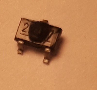
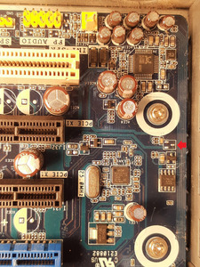
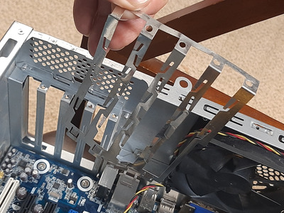
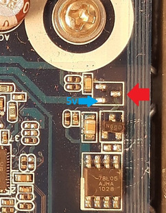
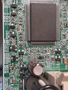
Was testing some hardware I had in the shop and was using my XP box and had a mishap. Had the machine off and was pulling out a video card (dual slot 1060 GTX) I just tested, and it somehow got all tangled up in the RF shield thingy of the cases expansion slots. I have since thrown that piece out, but long story short after trying to untangle it for a minute (system was off but not unplugged) magic smoke started pouring out. Looks like the bottom part of the video card caught on a component and it burned it. Any idea what part I need to put there and what it did? The board still posts now but haven't tried using anything in the PCIe slots or done any other in-depth testing.

20240514_202500.jpg
Filename
20240514_202500.jpg
File size
42.13 KiB
Views
254 views
File license
Public domain
20240514_202603.jpg
Filename
20240514_202603.jpg
File size
1.47 MiB
Views
254 views
File license
Public domain

Attachments

Reply 1 of 9, by Horun

User metadata
Rank l33t++
Rank
l33t++

Do not have an Intel DH55TC board so can not check the part.
Assuming everything works as it should that part would be connected to 5VSB if it had voltage and you grounded it direct with the shield (5VSB would be the only volts present if ATX PSU was off).
Should not effect the PCIE AFAIK and since the board boots it did not effect the power on stuff. Sorry is all I have at a quick guess....

Hate posting a reply and then have to edit it because it made no sense 😁 First computer was an IBM 3270 workstation with CGA monitor. Stuff: https://archive.org/details/@horun

Reply 2 of 9, by lowlytech

User metadata
Rank Member
Rank
Member

Well I plugged in my PCIe x16 video card and PCI sound card back in and they seem to work without issues. So maybe this goes to the onboard sound that I already had disabled in CMOS since I always had an Audigy installed in the PCI slot . The onboard LAN seems fine as well, but if it was standby voltage could it be for WoL ? Just trying to figure out what exactly I broke

Reply 4 of 9, by lowlytech

User metadata
Rank Member
Rank
Member

What would a p Channel mosfet purpose be in this section more than likely? If it is not stressing some other components on the board or the other 22a17 then i guess i can leave it as is, but i probably won't be able to stop thinking about it. So is 22a17 what i need to look for as a replacement?

Reply 5 of 9, by Karbist

User metadata
Rank Member
Rank
Member

This is dual 5v rail for the audio chip, 5v standby goes through this mosfet then a diode then it looks like to the input of the 5v regulator (78l05) and when pc is on, the input of 5v regulator should get power from 12v rail.

Reply 7 of 9, by Karbist

User metadata
Rank Member
Rank
Member

Yeah it should work fine, if you have a multimeter, measure the source pad of the mosfet when pc is off to confirm it's getting 5v.

20240514_202603.jpg
Filename
20240514_202603.jpg
File size
116.41 KiB
Views
99 views
File license
Public domain

Reply 8 of 9, by lowlytech

User metadata
Rank Member
Rank
Member
Karbist wrote on 2024-05-17, 15:20:

Yeah it should work fine, if you have a multimeter, measure the source pad of the mosfet when pc is off to confirm it's getting 5v.

20240514_202603.jpg

Yes just confirmed there is 5 volts present on the pad when the machine is not on. I have a few motherboards laying around that are donor boards, gonna go look and see if I can find that component without having to put in an order to Mouser.

Reply 9 of 9, by lowlytech

User metadata
Rank Member
Rank
Member

Well the only thing I can find on my parts boards seems to be N type Mosfets and not P type from google searching the few letters and numbers on these chips. Guess I may have to purchase a new one next time I put in an order for new components.

For kicks I reenabled the onboard audio and to my surprise it finds the hardware and it plays windows sounds normally. Fired up a game of Max Payne 2 and everything sounds normal there as well. I did measure the voltage on the pads where the component went while it was on and I have voltage on all 3 pads. The top single pad has 5.02v the bottom right has 5.07v and the left bottom pad shows 6.04v

Here is a few shots from my donor boards with the SOT-23 looking candidates that seem to be wrong for this application.

20240517_230454.jpg
Filename
20240517_230454.jpg
File size
1.7 MiB
Views
53 views
File license
Public domain
20240517_225905.jpg
Filename
20240517_225905.jpg
File size
1.31 MiB
Views
53 views
File license
Public domain