VOGONS


First post, by auron

User metadata
Rank Oldbie
Rank
Oldbie

hi, i hope somebody can help me with this. i have been attempting to recap my mt-32 (old) since there was some flickering on the lcd and i thought this is probably due to dried caps. unfortunately i'm a total noob at soldering and so i wound up breaking two vias by ripping off the barrels. they came right off when pulling out the cap. this happened on c32 and c70, positive side on both.

i'm hoping to be able to fix this mess by jumping some wires. from what i can tell there are only traces at the bottom going from those two vias. c70 seems pretty straightforward with the trace going straight to to the cpu, so i'm assuming i can just follow that: http://i.imgur.com/pEOlGjM.jpg

but c32 seems more complicated since the signal path is branching off here. http://i.imgur.com/rsLvXaT.jpg (the empty via is the broken one) what am i supposed to solder here in order to fix this?

here is a full mainboard pic for reference: https://upload.wikimedia.org/wikipedia/common … _1_PCB_View.jpg

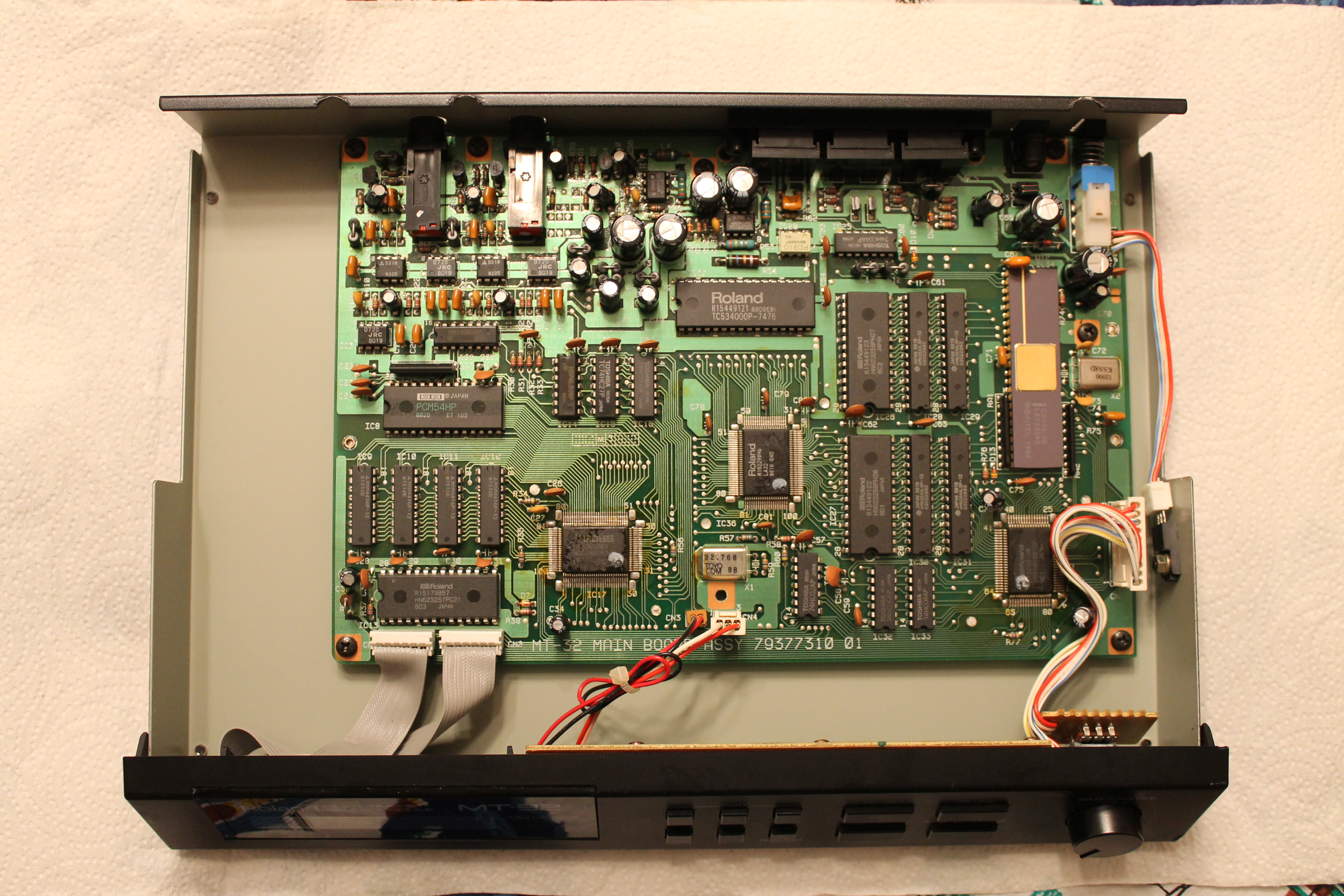
also can somebody share a good trick to clear a via from solder in general? am i supposed to use desoldering wick? im using a solder sucker but it doesnt work all that great.

Reply 1 of 8, by Jepael

User metadata
Rank Oldbie
Rank
Oldbie
auron wrote:

there was some flickering on the lcd and i thought this is probably due to dried caps.

A car analogy first. I don't know a lot about cars. If I think my car has some weird problem, and I don't know what is causing it, I don't start randomly changing parts to fix it.

Having said that, MT-32 has a linear power supply so caps don't wear out so much than in switch mode power supplies. I don't think you have dried caps unless you prove it 😀 Did you even try a different power supply? Does it otherwise work?

To fix it, use some fine single strand wire (I think I'd use something like Kynar 30AWG wire wrap stuff kind of thing for this, green color does not stick out much).

For C70 you can just solder the wire between the capacitor and IC pins where the trace goes.

For C32, I'd propably just solder a wire from the missing capacitor via to the resistor leg via on left of it.

You could clear a via from solder with solder wick, or solder sucker. Best way to use sucker is to apply heat from other side and suck from the other side at the same time.
If the solder does not seem to melt, the soldering iron could be too weak. I don't mean temperature, but watts, so it can't heat up the board enough. Sometimes the solder wick eats too much of the heat so the solder does not melt much so the wick does not suck it.

Reply 2 of 8, by auron

User metadata
Rank Oldbie
Rank
Oldbie

thanks for the reply. the mt-32 worked fine otherwise and i only used original roland psus on it. i don't know what the previous owner was using though as it came without a psu. it's pretty popular to use switching adapters with these synths nowadays and there certainly aren't many warnings on the net about this. the unit also might have had a fair bit of abuse as all the connectors were already resoldered on it. also, one of the central 1000µF capacitors had a bit of yellow powder on top of it that looked like dried electrolyte to me.

from working a bit more on this while waiting for the parts for that repair to arrive, i think the main problem was that i didn't bend the capacitor legs straight before desoldering them. when doing this, or when they are straight in the first place, it's quite easy to get it out in about 10 seconds with slow pulling and minimal thermal stress. on the ones i broke it took me several minutes, so it was inevitable that the barrels would get ripped out.

it also seems a big issue that the vias aren't designed equally for some reason. on the negative ends there is some square around it and these vias are really easy to clean, but on the positive ones that square is missing and these seem basically impossible to clean. not even after applying the wick 5 or 10 times or using the sucker the way you suggested. i ordered a better solder sucker so hopefully that will help. i'm using a generic 48w station at 370°.

what i've been doing so far to get new caps in is to heat up the closed via with the iron while pushing the lead in. it's a bad method but the only one that worked so far, and i didn't rip any barrels out with it. it probably helps that there is only very little solder on there that would heat the barrel up, compared to pulling the caps out where i used a ton of solder. i guess there is also the dental pick method but that seems even more crude.

when i go to soldering the wires in place, should i use some flux so that the wire sticks better to the capacitor end?

Reply 3 of 8, by auron

User metadata
Rank Oldbie
Rank
Oldbie

i was able to use a cap meter to check some of these caps i pulled out. capacitance was extremely close to what they are rated as in all cases which is surprisingly good news for 30 year old caps. esr was mostly about twice as high as the replacement ones (panasonic fc) and three times higher on the smaller sized ones (1.2 vs. 3.6 ohms on the 1µF). hard to say how much of that is due to wear but supposedly even 3.6 ohms is really good for a 1µF cap so i guess there is no urgent need for cap replacement on these synths after all.

Reply 4 of 8, by Jepael

User metadata
Rank Oldbie
Rank
Oldbie

Your soldering iron sounds like OK, and glad you are able to fix it. You don't necessarily need flux when just soldering wires to caps, as normally the solder contains some flux in it. If you do apply extra flux, you need to wash it out with something (some are solvent-based, some are water-based) otherwise it stays as sticky goo and might oxidize something.

By the way, did you change all electrolytic caps? At least the newer MT-32 does not have regular electrolytic caps on its audio outputs, but bipolar electrolytics. I don't know about older MT-32 as I don't have schematics and I don't want to open my MT-32.

Just a question regarding your cap meter, at what frequency did it measure the ESR? Some measure at around 100-120 Hz (for mains rectifying use) and some measure at kilohertz or few (for high frequency bypass use).

Reply 5 of 8, by auron

User metadata
Rank Oldbie
Rank
Oldbie

well, i haven't fixed it quite yet. still waiting for that wire and have replaced over half of the caps but the most daunting part about it is trying to bend the old capacitor pins in place without scratching any traces...

i was planning to use nichicon muse bp to replace the bipolar caps, these are supposed to be quite good. the cap meter was an atlas esr60, it uses 100 kHz, which is apparently the same way the cap manufacturers give their esr ratings according to the manual.

Reply 6 of 8, by auron

User metadata
Rank Oldbie
Rank
Oldbie

so, this turned out to be quite the odyssey... or, should i rather say, nightmare. 😵

i wound up doing quite a bit more damage to the board, and after repairing it i tried to power it for the first time; it didn't turn on. i discovered that i had stupidly connected plus to minus on the two 470µF caps instead of plus to plus, and after fixing that it would turn on with a blank screen. after a lot of continuity checking i discovered that one of the caps didn't have continuity, and i resoldered that, still no continuity... this is still a mystery to me as i'm pretty sure i didn't break that via, as otherwise the solder wouldn't stick so well to the bare pcb. anyway, patched that and around that time also managed to rip off the 7805 cable... resoldered it, what fun. but now the mt-32 works again. i just hope that all the tries with faulty soldering didn't cause any damage to the ICs, but i don't know nearly enough about electronics to assess that.

this is how the recap looks like: http://i.imgur.com/A3lu35v.jpg
and this is my shitty soldering job: http://i.imgur.com/epG0c50.jpg

oh, and lastly, the recap of course didn't fix these strange intermittent flickering pixels on the lcd that sometimes happen during playback. 🙄 but i think i at least learned a thing or two from that...

Last edited by auron on 2015-08-24, 19:16. Edited 3 times in total.

Reply 7 of 8, by Jepael

User metadata
Rank Oldbie
Rank
Oldbie

I think the green wire fits there nicely, quite unnoticeable. Good thing it works again, congrats!

Reply 8 of 8, by auron

User metadata
Rank Oldbie
Rank
Oldbie

well, shit... there is something wrong with it after all. when i tested it for the first time it seemed fine, but now i noticed how the left channel is silent during playback... and when i pull the right one out, suddenly the left one starts playing. or maybe it then does mono on the left output? i'll check continuity again on all points, but any idea whatsoever what area this could come from?

edit: actually this behavior disappeared after i restarted the unit, and right now i'm not able to reproduce it anymore... very strange. it's definitely not related to the plugs as i had replugged them, and it still did this.