First post, by squareguy

Rank
Oldbie
- Rank
- Oldbie
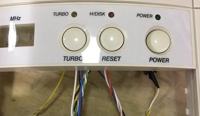
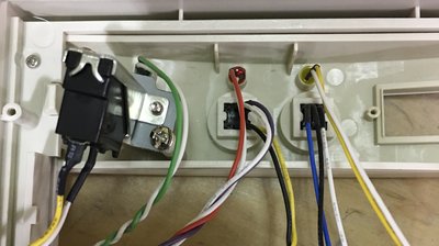
I have no idea what to do. There are no jumpers and it seems like some front panel LEDs and such hook directly too it. I should have taken pictures before I realized they probably weren't just jammed on there for no reason. The switches are odd too, like the reset button has two sets of wires. One going to motherboard and one going to LED, I think.
What on earth???
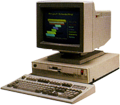
Gateway 2000 Case and 200-Watt PSU
Intel SE440BX-2 Motherboard
Intel Pentium III 450 CPU
Micron 384MB SDRAM (3x128)
Compaq Voodoo3 3500 TV Graphics Card
Turtle Beach Santa Cruz Sound Card
Western Digital 7200-RPM, 8MB-Cache, 160GB Hard Drive
Windows 98 SE