VOGONS


Reply 20 of 33, by muon

User metadata
Rank Member
Rank
Member
mdog69 wrote:

From practical experience
If you use an old configuration program, you can only select 8, 16 or 32k devices.
If you use an old configuration program on a 509B, chosing 32k device will result in a 16k window as per the hardware design.

mdog69, where can I get the "new version"? I have got the old configuration program for 3com.

Reply 21 of 33, by mdog69

User metadata
Rank Newbie
Rank
Newbie

The latest Etherdisk is 6.1 available at http://fog.bio.unipd.it/pub/Networking/Networ … om509-3Com509B/

The 3c5x9cfg.exe on that disc is the same version as the one I used to configure my card v3.2 - the only difference seems to be the diagnostics library version.
Neither version allows you to configure a 64k (27512 device). It would appear that 27512 support is "documented but not made directly accessible".
- it's shown in the technical document, but the configuration program doesn't let you select it.
I have a feeling that it was introduced for Lanworks BootWare roms to permit multiple protocol support on a single device.

Doesn't really change my recommendation regarding filling the device though.

Reply 22 of 33, by tayyare

User metadata
Rank Oldbie
Rank
Oldbie
mdog69 wrote:

... For 3C509 and 3C509B, pad out your image to 16k, and duplicate the image to fill the device....

Is there a non-Unix, "common joe" type method to make this happen in DOS or Windows? 😊

Thanks in advance

Last edited by tayyare on 2019-02-21, 07:46. Edited 1 time in total.

GA-6VTXE PIII 1.4+512MB
Geforce4 Ti 4200 64MB
Diamond Monster 3D 12MB SLI
SB AWE64 PNP+32MB
120GB IDE Samsung/80GB IDE Seagate/146GB SCSI Compaq/73GB SCSI IBM
Adaptec AHA29160
3com 3C905B-TX
Gotek+CF Reader
MSDOS 6.22+Win 3.11/95 OSR2.1/98SE/ME/2000

Reply 23 of 33, by keropi

User metadata
Rank l33t++
Rank
l33t++

Copy /b 16kb.bin + 16kb.bin + 16kb.bin + 16kb.bin 64kb.bin

This will copy a file called 16kb.bin four times and will create the file 64kb.bin

🎵 🎧 PCMIDI MPU , OrpheusII , Action Rewind , Megacard and 🎶GoldLib soundcard website

Reply 24 of 33, by mdog69

User metadata
Rank Newbie
Rank
Newbie
tayyare wrote:
mdog69 wrote:

... For 3C509 and 3C509B, pad out your image to 16k, and duplicate the image to fill the device....

Is there a non-Unix, "common joe" type method to make this happen in DOS or Windows? 😊

Thanks in advance

None that I know of. Might have more luck finding a tool written in C to do it under Linux.

In any case, using such a unicorn/tool to switch it into 64k mode is a waste of time.
All it does is allow bank switching between 4off 16k banks, which if you follow instructions, should be identical anyway!

Create a 64k image as detailed elsewhere using copy/b in DOS.
Burn the image to the device
Set the device size to 16k or 32k using 3c5x9cfg.exe and away you go.

Reply 25 of 33, by tayyare

User metadata
Rank Oldbie
Rank
Oldbie
keropi wrote:

Copy /b 16kb.bin + 16kb.bin + 16kb.bin + 16kb.bin 64kb.bin

This will copy a file called 16kb.bin four times and will create the file 64kb.bin

Ahh... sorry, I was asking about "pad out" part, not replicating a 16KB file into anything lik 32, 64KB files. 😊

GA-6VTXE PIII 1.4+512MB
Geforce4 Ti 4200 64MB
Diamond Monster 3D 12MB SLI
SB AWE64 PNP+32MB
120GB IDE Samsung/80GB IDE Seagate/146GB SCSI Compaq/73GB SCSI IBM
Adaptec AHA29160
3com 3C905B-TX
Gotek+CF Reader
MSDOS 6.22+Win 3.11/95 OSR2.1/98SE/ME/2000

Reply 26 of 33, by mdog69

User metadata
Rank Newbie
Rank
Newbie
tayyare wrote:
keropi wrote:

Copy /b 16kb.bin + 16kb.bin + 16kb.bin + 16kb.bin 64kb.bin

This will copy a file called 16kb.bin four times and will create the file 64kb.bin

Ahh... sorry, I was asking about "pad out" part, not replicating a 16KB file into anything lik 32, 64KB files. 😊

Sorry - I provided an answer to a question you didn't ask...

Two ways to pad out:
A Google for how to pad a .bin file throws up
http://little-scale.blogspot.com/2009/06/how- … d-bin-file.html
Not tried it myself - scroll down to the comments section and there's a reference to padbin.exe which looks like it might be easiest to use.

Second way, no binaries required - if you have an EPROM programmer
1) Choose any device which is 16Kx8 in size
2) Fill the programmer's space with zeros (e.g. "block fill"
3) Load the "short" image you have from PC into memory
4) Save the RAM image from the programmer's memory. You want to start at 0x0000 and either "end at 0x3FFF" or "length=0x4000"

Note that you can either pad with zeros (0x00) or ones (0xFF).
Padding with 0xFF means your EPROM programs faster (if you have a lousy programmer), but it then means that programs like MSD might incorrectly report that the padded area is not in use.
Padding with 0x00 means that MSD identifies the padded area as "may be available", which it isn't, but it at least makes you stop and think.

I used 0x00.

Reply 28 of 33, by tayyare

User metadata
Rank Oldbie
Rank
Oldbie
mdog69 wrote:
Sorry - I provided an answer to a question you didn't ask... […]
Show full quote
tayyare wrote:
keropi wrote:

Copy /b 16kb.bin + 16kb.bin + 16kb.bin + 16kb.bin 64kb.bin

This will copy a file called 16kb.bin four times and will create the file 64kb.bin

Ahh... sorry, I was asking about "pad out" part, not replicating a 16KB file into anything lik 32, 64KB files. 😊

Sorry - I provided an answer to a question you didn't ask...

Two ways to pad out:
A Google for how to pad a .bin file throws up
http://little-scale.blogspot.com/2009/06/how- … d-bin-file.html
Not tried it myself - scroll down to the comments section and there's a reference to padbin.exe which looks like it might be easiest to use.

Second way, no binaries required - if you have an EPROM programmer
1) Choose any device which is 16Kx8 in size
2) Fill the programmer's space with zeros (e.g. "block fill"
3) Load the "short" image you have from PC into memory
4) Save the RAM image from the programmer's memory. You want to start at 0x0000 and either "end at 0x3FFF" or "length=0x4000"

Note that you can either pad with zeros (0x00) or ones (0xFF).
Padding with 0xFF means your EPROM programs faster (if you have a lousy programmer), but it then means that programs like MSD might incorrectly report that the padded area is not in use.
Padding with 0x00 means that MSD identifies the padded area as "may be available", which it isn't, but it at least makes you stop and think.

I used 0x00.

Wow, that's the informtion I'm after. Thanks a lot for the detailed instructions, I'll try that this evening! 😀

GA-6VTXE PIII 1.4+512MB
Geforce4 Ti 4200 64MB
Diamond Monster 3D 12MB SLI
SB AWE64 PNP+32MB
120GB IDE Samsung/80GB IDE Seagate/146GB SCSI Compaq/73GB SCSI IBM
Adaptec AHA29160
3com 3C905B-TX
Gotek+CF Reader
MSDOS 6.22+Win 3.11/95 OSR2.1/98SE/ME/2000

Reply 29 of 33, by rjbrown99

User metadata
Rank Newbie
Rank
Newbie

This thread was incredibly helpful to me in getting this working, so here's a more detailed set of instructions on my process end-to-end.

1. Bought an XTIDE card that can also flash EEPROMs, in my case Blue Lava Systems XT-IDE rev 4.1. Note that this uses address 300h by default. https://www.bluelavasystems.com/xt-ide/

2. Bought a few new EEPROMs from Amazon, 28C256 chips since they could deliver quickly. 256kb, 32kx8. VERY IMPORTANT to note that EEPROMs have a specific orientation when installing, or you fry your EEPROM. Look for the small half-circle and line them up. I was today years old when I learned that and this is why I suggest buying a handful of extra EEPROMs. https://www.amazon.com/gp/product/B07PF9QH5K

2a. If you are using the new 256kb EEPROMs, make sure you change the switches on the Blue Lava card, it's configured to use an 8K EEPROM by default.

3. Grabbed XTIDE files from the correct site: https://code.google.com/archive/p/xtideuniver … lbios/downloads (I used beta 3)

4. Booted from floppy, ran xtidecfg, loaded the original bios from file, in my case ide_atl.bin. Configured it accordingly, saved it back to the original file. It's important to edit/update/save settings in this step before you build a larger/padded/combined file later.

5. Copied the new/saved ide_atl.bin to a Linux box. This file was 12288 bytes to begin with. The 16kb target space would be 16384 bytes, so we need to pad by 4096.

cp ide_atl.bin ide_at16.bin (make a backup)
dd if=/dev/zero bs=1 count=4096 >> ide_at16.bin (file should now be 16384 bytes)
cat ide_at16.bin ide_at16.bin > ide_at32.bin (the ide_at32.bin should be 32768 bytes)

6. Copy ide_at32.bin to a floppy with xtidecfg.com. Also make sure that floppy has 3c5x9cfg on it.

7. Boot from floppy and run xtidecfg.
Load bios from file (ide_at32.bin)
Flash EEPROM
Type 28256 (32kib)
SDP command None
Page size 4 bytes
Start flashing

8. Reboot with the XT-IDE card to make sure it works.

9. Reboot to floppy, run 3c5x9cfg and configure the NIC. Modify to a base address of your choice (making sure to avoid 300h if you plan to test the NIC+XTIDE card at the same time).
Boot prom 32KBytes, address C8000h.

10. Use a chip puller to remove the EEPROM and install it on the network card. Be very sure you line up the half-circles or you fry the chip.

11. Remove the XT-IDE card and boot with just the network card, the BIOS should load for you.

Hope that is helpful for someone else.

Reply 30 of 33, by darry

User metadata
Rank l33t++
Rank
l33t++

Is it possible to modify an ISA option ROM to load as a PCI option ROM ? I know that PCI option ROMs are linked to a device ID, but are there major differences in structure otherwise ?
I ask because I failed miserably in appending XT-IDE as an ISA option ROM to my Asus P3B-F's BIOS (it just won't run, I've got another thread running about that). I am also starting to question whether my board actually supports ISA option ROMs, but I have no ISA NICs to test with (can't find my 3COM 3C509). Anyway if appending to system BIOs could work, that would be even better than using a NIC's bootrom, IMHO .

Reply 31 of 33, by Jo22

User metadata
Rank l33t++
Rank
l33t++

Re: IDE disk-on-module + 386

Also, if you download an official XTIDE Universal-BIOS from the net, make sure you have it loaded in its DOS configuration program first.
- It's necessary to save the settings (even if no changes were made), because the software adds a valid checksum which the PC/AT BIOS is looking for.

"Time, it seems, doesn't flow. For some it's fast, for some it's slow.
In what to one race is no time at all, another race can rise and fall..." - The Minstrel

//My video channel//

Reply 32 of 33, by makary23

User metadata
Rank Newbie
Rank
Newbie
muon wrote on 2019-02-19, 09:41:
Now I have another problem. […]
Show full quote

Now I have another problem.

I would like to use a mechanical Hard disk (no SSD) with my older motherboards (286, 386). As you know actually there is not available mechanical IDE Hard disk. I thought in SATA HD with SATA to IDE adapter. it works properly in my Pentium motherboards with integrated IDE controllers, but if the motherboard has not IDE controller and I have to plug a multi io+ ide doesn't works properly.

The hard disk is availabe in the fdisk DOS command, but I do some partition, when the computer resets to proceed with the format of the new partitions , there is no partitions: the table of parttions is never saved ¿¿??

Has something similar happened to someone?

Hi.
same happened to me. how did you solve this problem? see my post.
XT-IDE doesn't see the partition or 386 doesn't see it?

Makary23

Reply 33 of 33, by Sudos

User metadata
Rank Newbie
Rank
Newbie
mdog69 wrote on 2019-02-19, 13:03:
Short version: […]
Show full quote

Short version:

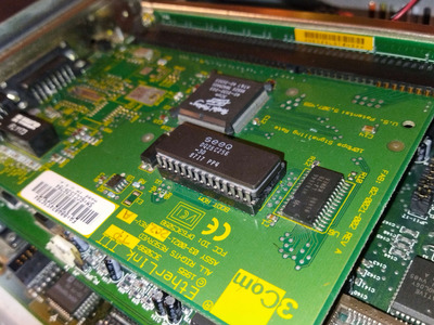
I got my XT-IDE BIOS working in a 27256 filled with 2x16k images, installed in a 3C509B.

Long version:

OK, here's what I've learned so far.
I have a 3C509B-Combo - the important thing here is that I have a 3C509B not an older 3C509.
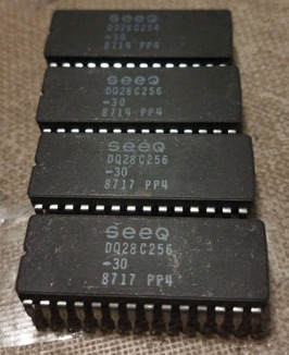
I have an old Atmel 27C256R (120ns) EPROM - 32Kx8
The aim of the game was to use XT-IDE to allow me to access a 4.3Gb "mechanical" disc drive.

I also got my hands on the "Etherlink III Parallel Tasking ISA, (blah blah) Adapter Drivers Technical Reference"
available at https://www.janwagemakers.be/PIC18F452_3COM_3 … rnet/3c5x9b.pdf

From the Technical Reference document (and informed by 2764, 27128, 27256 datasheets) I found out the following:

3C509B
Supports all 28 pin ROMs - 2764, 27128, 27256, 27512 (No need for modified EPROMs or NICs)
Can be configured to use "8k, 16k, 32k and 64k" ROMs
If you select a 32k or 64k device, the device has a 16k UMA window, and the NIC uses a "ROM Option" register to allow bank switching in that window.
This means that the A14 and A15 pins on the ROM socket are driven, and are not floating.

3C509
Does not explicitly support 27512
Supports all other 28 pin ROMs - 2764, 27128, 27256
Can be configured to use "8k, 16k, 32k" ROMs
If you select a 32k device, you get a 32k UMA window, which means A14 is determined by the ISA bus, and the whole device is exposed.
It is possible that for 8k and 16k modes the A14 pin (pin 27) is tied to Vcc (this pin is "not program enable" which is usually set to Vcc for read operations)
It is highly likely that the A15 pin (pin 1) is tied to Vcc (this pin is Vpp which is usually set to Vcc for read operations)

From practical experience
If you use an old configuration program, you can only select 8, 16 or 32k devices.
If you use an old configuration program on a 509B, chosing 32k device will result in a 16k window as per the hardware design.

If you do not have a ROM installed in the NIC, the configuration program will give the warning message that others have seen.
(Hint: The program probably looks for the 55 AA signature at the ROM base address, and nothing else)

I did the following:

Target PC configuration
* Installed the 3C509B with no OM onboard
* Booted the system with an old MS-DOS hard drive (540Mb) and ran 3C5X9CFG to select 16k ROM at C8000H
Got the warning message, went ahead anyway.

XTIDE image preparation
* Copied IDE_386L.BIN and XTIDECFG.COM to an MSDOS virtual machine. This created a new IDE_386L.BIN which was 10k in size.
* Copied the new IDE_386L.BIN file to my Linux box, padded it out to 16k (dd if=/dev/zero bs=1 count=6144 >> IDE_386L.BIN )
* I then created a 32k image file (cat IDE_386L.BIN IDE_386L.BIN > IDE_386L_27256.BIN
* I then loaded this into my EPROM programmer and burnt the EPROM.

Testing the EPROM
* Powered off the 486
* Inserted the EPROM in the card
* Got the expected output from the new BIOS extension and Successfully booted off the 540Mb
* If I have any problems from this point, it's down to XT-IDE.

So, to end:
The 3C509B drives the EPROM A14 and A15 lines, no need to modify EPROM or card.
The 3C509 is a little less clear - in 32k mode, A14 gets driven. In other modes, A14 probably gets forced to +5v, and A15 is probably tied permanently to +5v, but it will need to be tested.

For 3C509 and 3C509B, pad out your image to 16k, and duplicate the image to fill the device.
For 3C509B you can use 27256 or 27512 - and you can either select 16k or set the actual device size.
For 3C509 stick to 2764 or 27128 unless you want to do some testing and use a 27256 or 27512 after selecting 16k device.

If you duplicate the image, and you know that the A14/A15 lines are being driven high or low, you can be certain that whatever the card does to the pins, you will always
get a 16k BIOS extension made available to the ISA bus, and you don't need to concern yourself whether each pin is high or low.

Wanted to shove my two cents in this thread because it was immeasurably helpful to me, and hopefully my experiences are of help to someone else down the line as the ones previous to this message were for me.

I bought some new old stock SEEQ DQ28C256-30 EEPROMs off eBay a couple weeks ago and finally got a XGecu T48 in to program them, as not a single XTIDECFG utility will work with these chips at all, possibly because the chips I have are 300ns and the utility is assuming for something a bit faster.
As others have done like quoted above, set the 3C509B with 3c5x9cfg for your choice of boot address as you've configured in your ROM file. in my case, it's D8000h and I chose the 16k size option. As this is a 32k ROM, we need to pad the file to 16k and then duplicate the ROM to fill the remaining ROM space.

Where my experiences differ is, I used a program called padbin to pad out ide_atl.bin found at this blog post comment or directly. it seems that the creator rewrote a piece of code that came with a "gbfs" zip file meant to pad gameboy ROM files. in this case the syntax to use is

padbin.exe 16K ide_atl.bin

and you should end up with a 16K ROM file. Alongside the EXE file in the zip is a .cpp source file, and the original code is GPL'd.

From here I stuck it through HxD Hex Editor and just had it concatenate the file twice on itself (no need to open the ROM in the program, just go to Tools > File Tools > Concatenate... and it should give you a prompt to add the file to twice and a box to name the output file and where.)

Took this, opened it in XGpro (in my case, v12.57) and selected an Atmel AT28C256@DIP28 as the closest living relative of the destination chip, as Atmel bought all of SEEQ's ROM stuff in 1994 or 1997 IIRC when they restructured.
I erased the chip a few times to make sure for-sure it was blank, did a blank check, and wrote the file to the ROM. Don't forget to reverify afterwards of course. Note that this chip doesn't need protection disable/enable done as allowed by the program, you can safely uncheck both of those as this chip predates software data protection schemes.

Popped it in, and it worked. it just worked, the first time, and every subsequent boot after.
Something to note, on all 4 of my ROMs, there's a Silicon Signature stamped on the underside, and some ROM flashers are able to read this as an ID and identify the chip. XGpro doesn't know how to do this for this chip yet but I'm hopeful to get them to add support in the future for such a thing as it's kind of important.

Another thing to note is that on all 4 of my ROM chips, address bit 0x7FC0h is stuck at FF no matter what I do. In this case it's fine, as the ROM contents do not spill out into here and the padding is all FF in that section. I blame XGpro for this slight blunder as it doesn't 100% support this chip but does support the chips that came after it. 0x7FC0h is the Chip ID byte on this ROM, which seemingly needs +12v to write. on an Atmel AT28C256, 0x7FC0-0x7FFFh are reserved for chip ID and need the extra write voltage, if memory serves.

Attached is a picture of all of the ROM chips I have of that SEEQ variety. This was only meant to be a proof of concept to show that the T48 can properly program these enough to work, and I wasn't expecting any of this to work as 300ns is way slower than most other ROM chips ever used in an XT-IDE setting... The OG Rev1 Hargle cards used SEEQ 250ns plastic-encapsulated EEPROMs for a time, but these were found to be very unreliable as time went on and writes were performed to them. As the ones I have here are from pretty much year 1 of the 28C256 being a thing for SEEQ in a real capacity (not to mention being the ceramic-epoxy-ceramic Oreo variety), I'm expecting them to last a bit longer, but time will tell.

Attachments

  • IMG_20230701_021222-01.jpg
    Filename
    IMG_20230701_021222-01.jpg
    File size
    802.77 KiB
    Views
    828 views
    File comment
    Installed in 3C509B, notch towards the ports.
    File license
    Public domain
  • DQ28C256-30.jpg
    Filename
    DQ28C256-30.jpg
    File size
    311.13 KiB
    Views
    830 views
    File comment
    4x DQ28C256-30. 1987-14/17 date codes.
    File license
    Public domain

gi3jzt-2.png
qxkaxq-2.png