First post, by Brutus814
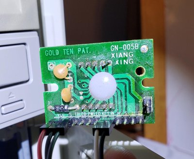
Hello again everyone. I really appreciate everyone's help with my previous post. I finally got everything up and running. The key was a new processor. I am putting the finishing touches on my build and I am trying to get the front panel MHz LED Display to work. I know these are just for show and don't really add anything performance-wise, but I'd like to complete the look. This is what the back of the LED board looks like:
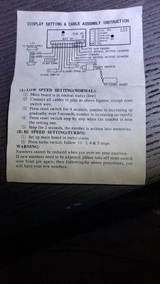
I also have the LED board instructions that came with the case:
I have connected the two left-most connectors to 5V red and black wires from a molex connector. This has turned on the LED. My front panel reset switch has two sets of 2-pin wires coming off of it. One goes to the motherboard reset header and works. The other I have connected to the LED board and it will change the digits on the LED as described in the instructions. For reference, my motherboard is a Chicony CH-471a ver. 3.
So, I can can set the LED to show 66 and everything is good. The power LED on the front panel works and the turbo switch works to downclock my CPU when benchmarking it. It will also toggle the turbo LED on the front panel. The problem is that I can not get the front panel LED to change it's value (to 33) when the turbo button is pressed. I followed the instructions to set it and it didn't work. I tried connecting the "panel turbo LED" and "panel power LED" wires as shown in the instructions and it didn't help. I didn't think this was going to be needed anyways, since they can be connected to the motherboard and work as intended that way. The only other connection is listed as "To M/B Turbo" on the instructions. It is only one wire. I have assumed that this is somehow referencing the turbo switch. My front panel has two 3-pin wires coming from the turbo switch. One of them I have connected to the motherboard and it will toggle the CPU's frequency appropriately. The other one, I have connected all 3 wires individually to the one "To M/B Turbo" pin on the LED board and it will not change the display when the turbo button is pressed. I am not sure what the right-most 4 pins on the board are used for. There was a jumper on the "Lo Signal Active (Jumper" and "Commo" pins when I bought the case.
Also, right above the "To M/B Green" pin (which I haven't been using) there are two more pins labeled J1 on the actual board and labeled as "Tub. SW" on the instructions. Interestingly, when I place a jumper between these two pins, the LED will display the second value (I set it to 33 when this jumper is shorted and it will stay at this value). When I remove the jumper, the LED will again display 66. I have not found any association between this and pressing the turbo button however.
Anyone have any ideas? If you would like any further info, let me know!
Thanks again for your help!