VOGONS


First post, by Pickle

User metadata
Rank Member
Rank
Member

I have a couple of these cards and i plan to use one to boot off of compact flash on a 386SX.
I found the wiki page ( I think i was little too quick) and just ordered some AT28C64's which are 28 pin:

Boot ROM
This card's boot ROM socket takes a standard 32-pin EEPROM chip, as well as 28-pin EEPROM chips such as the 28C64. It has been tested extensively with the 28C64 chip flashed with XT-IDE BIOS images, both XT and AT versions. It is a reliable way to boot from a modern era hard drive connected to an XT or AT class system whose BIOS would not natively support it.

So im doubting if the socket just takes the 28 pin eeprom i have. Some pins are the same, but i have feeling i might need to create an adapter. I wish the statement went into a little more detail or had a link.
I dont want to plug them in until I figure it out.

I also wonder if it possible to write via the nic card. (I know about the eeprom writers)

Does anyone else have some experience with a setup like this and have any suggestions?
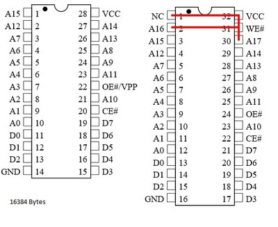
Attachments

  • at28c64.PNG
    Filename
    at28c64.PNG
    File size
    13.36 KiB
    Views
    835 views
    File license
    Public domain
  • jedec32.PNG
    Filename
    jedec32.PNG
    File size
    59.01 KiB
    Views
    834 views
    File license
    Public domain

Reply 1 of 5, by Horun

User metadata
Rank l33t++
Rank
l33t++

I have very limited experience with these but if pre-programmed a 28c64 will replace a 27c64. You fit the ROM in socket like others with base at end leaving 1/2 and 31/32 open (for a 32 DIP socket).
Pin 30 in a 32 pin socket should also be VCC which will match up to pin 28 on DIP 28, what you do not get is the Write-Enable line since it is tied to A14 using DIP 28 so you must pre-program the EEPROM. That is all I know...

Hate posting a reply and then have to edit it because it made no sense 😁 First computer was an IBM 3270 workstation with CGA monitor. Stuff: https://archive.org/details/@horun

Reply 2 of 5, by Cyberdyne

User metadata
Rank Oldbie
Rank
Oldbie

I usually use scavenged Flash bios roms from motherboards. Then hotflash them in one of a working motherboard with XTIDE or Blop boot, or even mini DOS. Just repeat the needed flash as much as needed. 8KB minimum XTIDE you just have to COPY 8kb + 8kb ..... as long as you get a 512kB binary to hotflash. Use UNIFLASH 1.4. Then you short those pins underneath. Put it is a LAN NIC boot rom socket. And configure the size. Thats about it.

Attachments

  • bootrom.jpg
    Filename
    bootrom.jpg
    File size
    51.39 KiB
    Views
    788 views
    File comment
    32pin to 28pin
    File license
    Fair use/fair dealing exception

I am aroused about any X86 motherboard that has full functional ISA slot. I think i have problem. Not really into that original (Turbo) XT,286,386 and CGA/EGA stuff. So just a DOS nut.
PS. If I upload RAR, it is a 16-bit DOS RAR Version 2.50.

Reply 3 of 5, by Pickle

User metadata
Rank Member
Rank
Member

thanks, just knowing the pin alignment is a great help. Makes sense now why those are marked NC. I was wondering which had to line up right gnd or vcc.

my idea was to try and use a pic processor to program the flash eeprom with a host pc over serial. I already have the pic tools so thought it might be fun project while being cheap.

Reply 4 of 5, by Jo22

User metadata
Rank l33t++
Rank
l33t++

Hi! It's late (or very early) and I'm a bit sleepy, but from what I remember..

EEPROMs and Flash ROMs should be backwards compatible in read-mode.

You can use a binary copy of the same and double it (mirror it).
COPY /B ROM.BIN + ROM.BIN BIGROM.BIN

This works fine, but may take up twice the space in 640-1024KB area.
Edit: Unless the NIC uses a limited address range, of course.
Haven't tried this yet, though. 😅

With some EPROMs/EEPROMs/OTPROM etc, you can take the BIGROM file, write it normaly into the chip an then do the following:

Tie the last address pin to ground or vcc.
This will cut the address range of the chip in half. You can also use this to select the upper/lower half, I believe.
This way, only one part of the BIGROM data can be read out by the network card.
The chip now behave like a chip half its size.

Anyway, please please double check what I said.
In my case, I used a 27C128 OTP that acted like a 2764, if memory serves.
Again, I'm sleepy and can't check right now.
From what I remember, I only had to add a little solder blob between two nearby legs.

Some more information:
https://ist.uwaterloo.ca/~schepers/sockets.html

"Time, it seems, doesn't flow. For some it's fast, for some it's slow.
In what to one race is no time at all, another race can rise and fall..." - The Minstrel

//My video channel//

Reply 5 of 5, by Pickle

User metadata
Rank Member
Rank
Member

so i ended up getting the TL866II plus programmer. Ive programed my 28C64B with the ide_386.bin. This should match my chip well at a size of 8 kb.
Ive padded the end with 0's. Ive tried the chip in 2 different 8/16 cards and in a 386 and 486 machine. I cant get it to boot at all.
The only option i really see is in the softset2.exe program to specify the boot rom address. There are quite a few options, but ive been going for D000.
All of the address ranges are 0x1FF in size. There is also an option for the rom program, but these appear to be old type programs so i dont think i need them.
I didnt think this would be that hard, but it still would be great to find someone who is using this card i this way.

Edit: I cant figure out why this wont work. Clearly the card is supporting 8k roms with the range of 0x200(0). I could actually see the xt bios data through umbinfo when the shadow ram was on. But seems like something on the card just doesnt work, see the xt bios data through umbinfo when the shadow ram was on. But seems like something on the card just doesnt work, even though networking with the packet driver has.even though networking with the packet driver has.
I checked the voltage on vpp, vcc lines and its 5 V. I even used a winbond flash chip and no change. I tried a second atmel chip no change. Tried 0x00's and 0xFF's for the alignment space.
Im going to get a 3com etherlink 3, since those seem to be popular.

Edit #2
Finally! I figured it out and it came down to the version of xt ide bios. The whole time i was trying to use the latest build v604. Went back to the v2 beta release and worked perfect. Now onto installing an OS and finally booting this thing.