VOGONS


First post, by Murugan

User metadata
Rank Oldbie
Rank
Oldbie

Last week, I was completing this 486DX-33 build.
Everything works except the mouse. After some digging around, I found an older post here regarding the same issue. The problem there was no - 12V and indeed, with my POST card, the - 12V led was off.
So I used my multimeter on the - 12V pin of the AT connector and the B7 pin of an ISA slot and there is no continuity.
The VARTA caused damage (why wouldn't it) so I started tracing where the break is and this is where my question comes.
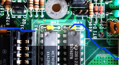
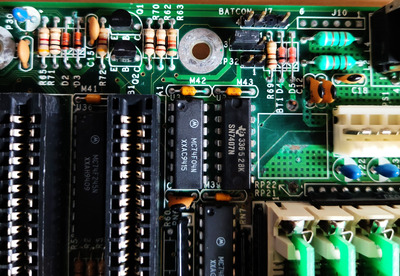
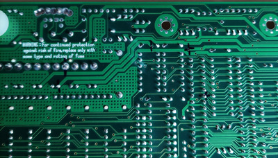
In the picture, the 2 vertical lines that I placed, is till where I could follow the - 12V line from the connector (starting under the word 'rating') . It seems to pass a blue cap (visible on the topside picture) and ends between the axial tantalum looking thingies M42 and 43 (sorry don't know what they are since I have limited skills).
The crosshair lines represent the path I followed from the - 12v pin of the first ISA slot towards the AT connector.
Is it safe to place a bodge wire from the leg of the blue cap to pin B7 of the first slot?

I did a repair on another board last week with also no -12v from a battery leak but there were no components between both VIA's.

Attachments

My retro collection: too much...

Reply 1 of 6, by Imperious

User metadata
Rank Oldbie
Rank
Oldbie

I don't think anyone here will give You a definitive YES to that question. We can't see enough.

It does look though as though that may be the case from looking at the top view. That point should be under M43 then and then go to just below where it says
A1 next to M42. Maybe You can get a better look from the top. Having said that though it's unlikely You will get a broken connection where there is clearly no corrosion.
I don't like the look of Tantalum capacitor P30, make sure it's ok, not shorted.

One Hint I can give is based on a repair to an XT motherboard I recently did. The capacitors on the negative rails should have their + pins grounded
and the - pins attached to the -12 -5 volt rails.

Have a look at the jumper next to the screw hole, it's right in the area You are looking at, maybe jumpering the wrong pins?

Atari 2600, TI994a, Vic20, c64, ZX Spectrum 128, Amstrad CPC464, Atari 65XE, Commodore Plus/4, Amiga 500
PC's from XT 8088, 486, Pentium MMX, K6, Athlon, P3, P4, 775, to current Ryzen 5600x.

Reply 2 of 6, by wiretap

User metadata
Rank Oldbie
Rank
Oldbie

That 7407 buffer chip doesn't look in the best shape either, with corrision on both sides of the board in its location. I'd definitely replace that since I'm sure it has worked its way inside the chip through the legs.

For every component in that area, you'll want to test from the back side of the board. Check capacitors for shorts, check the resistances to make sure they match the color bands, and check the diodes for proper voltage drop. (diodes there are probably just for the battery circuit)

Not sure what transistor Q1 and Q2 are for, but I'd replace those for fun since they are quick/easy/cheap, and seem to be in the impacted area of corrosion.

Point to point tests can be done for trace breaks, but it doesn't appear anything is that far corroded -- my Amiga 2000 looked like Alien puked on the board and it only had two traces that needed repaired. What you'll find more often is the case, is the via holes get corroded out to the point where they aren't connected anymore. That can be fixed by running some 36-40ga wire through the hole and connecting to the trace just away from the via where you still have good copper.

90% sure your problem is in the via hole, at least from my experiences from repairing corrosion impacted boards. Focus your troubleshooting on the -12V line through vias in that area.

Otherwise, it would help to see the motherboard manual for the board, since as Imperious pointed out, the jumper may have something to do with it -- however it would be weird to have a jumper related to disabling -12V.

My Github
Circuit Board Repair Manuals

Reply 3 of 6, by Murugan

User metadata
Rank Oldbie
Rank
Oldbie

Hmmmm as I stated before, I can do some basic repairs but I really need to train on my multimeter use. I have another working 486 board so for now I'll probably put that one in the build and keep this one for more troubleshooting.

Afaik, the jumper will be for selecting internal or external battery. The manual is online so I'll have a look at it.

My retro collection: too much...

Reply 4 of 6, by snufkin

User metadata
Rank Oldbie
Rank
Oldbie

Looks like just the two vias between those points, so probably one of those failed. I thought at first the -12V line headed up to JP32, but it looks like the via doesn't connect with that track (I lined up the front and back photos to draw in the bottom -12V traced so far). Looks like a via comes up under M43, then a top surface track to just under the ISA A1 corner. Given the corrosion in the area, I'd probably look under M43 first to confirm where the track goes and to check the via (and repair if it's failed). Then, even if things are generally working, it's probably worth changing, or at least cleaning and testing, anything that's corroded.

Broken__12v.jpg
Filename
Broken__12v.jpg
File size
140.55 KiB
Views
399 views
File license
Fair use/fair dealing exception

If I needed the board working right now, and didn't mind some risk, I'd solder a wire between the vias. But that's leaving a problem to grow.

Reply 5 of 6, by Murugan

User metadata
Rank Oldbie
Rank
Oldbie

As far as I saw,everything worked but the mouse.
Gave the area a good scrub with vinegar and a toothbrush, rinsed with IPA and there is contact all the way now!
Going to recheck tomorrow when it's completely dry again.

My retro collection: too much...

Reply 6 of 6, by Murugan

User metadata
Rank Oldbie
Rank
Oldbie

Last update. Placed a bodge wire between the cap that was connected to the - 12V line and B7 pin of the first ISA slot.
No boom and smoke so far and the mouse works again.

My retro collection: too much...