VOGONS


Reply 20 of 89, by stuvize

User metadata
Rank Member
Rank
Member

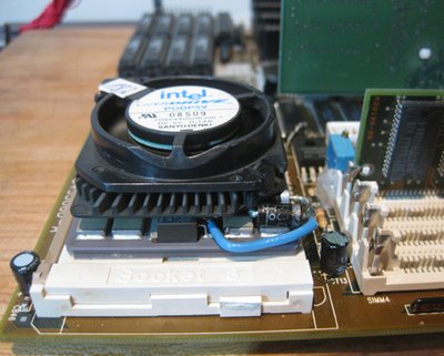
Is it JB weld I noticed it was metallic whatever it was solvents even acid did nothing to it I used a hard rubber buffing wheel for the Dremel it also went through extra solder and made it nice and smooth, the ceramic that the CPU is made out of is very hard the buffing wheel doesn't do anything to it other than polish it. It's interesting that you measured those high voltages 4.90 V is probably more than CPU needs to run stable at 100mhz also you mentioned in another thread that you were able to chill a unmodified POD and get a successful Quake demo at 100mhz heat seems to be destabilizing the POD a different VRM to give 3.60-4.00 V may be the way to go, I have read of people putting different VRM on the mobo to OC AM5x86 and other 3.3 V CPUs, I like the external VRM idea too. In theory the POD should take 5 V but these are more or less the reject socket 4 cores
Reply 21 of 89, by feipoa

User metadata
Rank l33t++
Rank
l33t++

A POD83 should work with 5 V? Won't it overheat?

I decided to sacrifice the sharpness of one of my wood chisels to remove the thermal epoxy. It came off quite easily with a few blows.

How do you know this is JB Weld? The thermal epoxy that Intel used may just have the same colour as JB Weld, but be something entirely different. I think Omega Engineering makes some high quality thermal epoxy that is grey colour. They also make one with slightly less thermal conductivity than the grey one, which is white colour. The problem I have with all of these epoxies is the shelf life. Usually 2 years max.

Plan your life wisely, you'll be dead before you know it.

Reply 22 of 89, by stuvize

User metadata
Rank Member
Rank
Member

I don't know if was JB weld for or not just seem to metal based. As for the POD at 5V I keep forgetting that the socket 4 PODs are 3.3 V not 5 V like the first Pentiums 60/66mhz, but according to literature of the time the socket 3 and 4 PODs were built to same specs of the 5 V generation of Pentiums so that also gets me mixed up sometimes. I actually didn't know about socket 4 until about a year ago when I found a socket 4 desktop in a dumpster finally found the proprietary cache module for it too.

Reply 23 of 89, by feipoa

User metadata
Rank l33t++
Rank
l33t++

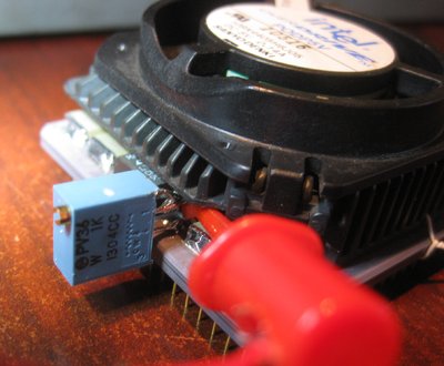
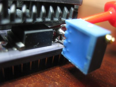
I have determined that the VRM on the POD83 is normally fixed at 3.50 V. The 4 SMD components on the cermaic package are all 3 uF capacitors. To increase the voltage from 3.50 V using the POD's voltage regulator, splice in a variable resistor (trimmer) in series on the VRM's GND pin. I used a 1K trim pot. This allows voltage adjustment from 3.50 - 5.0 V. The problem is that the POD's VRM can only output so much current, which seems to limit the coltage increase to 3.73 V on my system (at load). Even if you increase the voltage to 3.8+ V, under load, the voltage drops to 3.70-3.73 V. Note that the red clip in the photo is so that I can measure the voltage on the VRM's centre pin.

For this modification, I selected one of my POD chips which doesn't quite cut it at 100 MHz. Before the mod, DOS Quake would not load. After upping the voltage to 3.73 V, DOS Quake loads and begins the timedemo, however it crashes shortly thereafter. So this mod may work for you if you only need an extra 0.1 to 0.2 V. If you need more voltage, it might be best to change the POD's VRM entirely, preferably to something which can output up to 5A. Note that the value of the trimmer is approx. 30-ohms with a 3.73 V output.

Alternately, you might try following the original approach, which cuts the 5V line from the POD's VRM, but adding one or two diodes in series prior to bridging to the "3.3V" pin on the VRM. I might try this with some 6 A diodes I located in my bin.

POD_Trimmer_Mod_1.jpg
Filename
POD_Trimmer_Mod_1.jpg
File size
264.08 KiB
Views
2060 views
File license
Fair use/fair dealing exception
POD_Trimmer_Mod_2.jpg
Filename
POD_Trimmer_Mod_2.jpg
File size
213.25 KiB
Views
2060 views
File license
Fair use/fair dealing exception

Plan your life wisely, you'll be dead before you know it.

Reply 24 of 89, by stuvize

User metadata
Rank Member
Rank
Member

It makes sense that the POD needs more Amps rather than Volts, many modern motherboards are made with high output components to give better overclocking stability at a lower voltage. Feipoa I am glad you took a interest in this because I have limited knowledge on circuitry

Reply 25 of 89, by Anonymous Coward

User metadata
Rank l33t
Rank
l33t

tried a 50/50mhz boot like I had done before by pulling the fan but the fan signal seems to be null with all the on chip VRM circuitry gone it will boot at 2.5x multiplier with or without the fan.

I'm having difficulty understand this. Are you saying that with the surface components removed, the POD now defaults to 2.5X without the need for a fan signal?

"Will the highways on the internets become more few?" -Gee Dubya
V'Ger XT|Upgraded AT|Ultimate 386|Super VL/EISA 486|SMP VL/EISA Pentium

Reply 26 of 89, by feipoa

User metadata
Rank l33t++
Rank
l33t++

SMD components are required for voltage stability. In fact, without the SMD components, I only receive 2.6 V from the VRM. Putting the SMD components back, I get 3.5 V.

Plan your life wisely, you'll be dead before you know it.

Reply 27 of 89, by stuvize

User metadata
Rank Member
Rank
Member
Anonymous Coward wrote:

tried a 50/50mhz boot like I had done before by pulling the fan but the fan signal seems to be null with all the on chip VRM circuitry gone it will boot at 2.5x multiplier with or without the fan.

I'm having difficulty understand this. Are you saying that with the surface components removed, the POD now defaults to 2.5X without the need for a fan signal?

Yes it does not need the fan signal now, I don't know what else would have made it go to 2.5x it happened after I removed the components

Reply 28 of 89, by feipoa

User metadata
Rank l33t++
Rank
l33t++

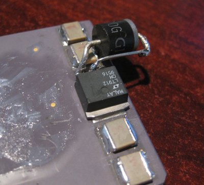
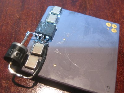
I added a 6 ampere diode as the bridge between the "5.0 V" node on the POD's ceramic surface and the "3.3 V" node on the POD's ceramic surface. Also, I cut the VRM's lead which connects to the "5.0 V" node. The voltage drop from the diode allows the POD to run at 4.00 V internally instead of 3.50 V (the default value). Note that "5.0 V" and "3.3 V" are just labels I used in my diagram to define certain nodes on the POD. Coming into the POD, I measure ~4.90 V. This means the diode is dropping ~0.9V at whatever current is going through it, probably 3.5 - 4.0 A.

6 ampere diodes are quite large, having a package size of 9 mm diameter and 9 mm long. For someone else who trys this, you might want to look for 4 or 5 A diodes. I have some 3 A diodes, which are quite a bit smaller, however they are only rated for 3 A continuous and might burn up.

The POD spec sheet mentions that at 25 MHz, the POD requires 1.9 A max. At 33 Mhz, it requires 2.8 A max. At 40 MHz, perhaps ~3.7 A max?

I have run GLQuake in autoplay mode for 25 minutes without any crashes. A good experiment would be to see how low of voltage is needed for stability.

POD_Diode_Mod.jpg
Filename
POD_Diode_Mod.jpg
File size
313.35 KiB
Views
2024 views
File license
Fair use/fair dealing exception

Plan your life wisely, you'll be dead before you know it.

Reply 29 of 89, by feipoa

User metadata
Rank l33t++
Rank
l33t++

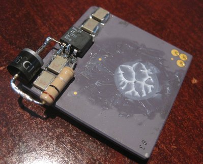
I decided to add a resistor in series with the diode to trop the voltage from 4.0 V to something between 3.7 and 4.0. I found that adding a 0.1-ohm, 2W resistor dropped the CPU's internal voltage to 3.72 V (under load) and 3.82 V (DOS idle). Unfortunately, GLQuake crashes after about 2 minutes. A 2-watt, 0.05-ohm resistor in series would probably do the trick for the minimum stable voltage, which I suspect is 3.80 V under load. Unfortunately, 0.1-ohm is my smallest resistor, other than 0-ohm, that is.

POD_Diode_Mod_2.jpg
Filename
POD_Diode_Mod_2.jpg
File size
345.25 KiB
Views
2011 views
File license
Fair use/fair dealing exception

For now, I think I will just leave the single 6-ampere diode in place and run the chip at 4 V. It seems stable.

POD_Diode_Mod_3.jpg
Filename
POD_Diode_Mod_3.jpg
File size
272.6 KiB
Views
2011 views
File license
Fair use/fair dealing exception

I also have a POD83 which runs without modification at 100 MHz. I wonder if it runs so well because of the CPU dye itself (a good quality fab job), or could it be that the particular VRM on that POD can handle the extra current better?

Plan your life wisely, you'll be dead before you know it.

Reply 31 of 89, by feipoa

User metadata
Rank l33t++
Rank
l33t++

I would have tried that but I only have exactly one 0.1-ohm resistor. It was a desoldered components from something long ago. The next lowest resistor I have is two pieces of 0.4-ohms.

Plan your life wisely, you'll be dead before you know it.

Reply 32 of 89, by alexanrs

User metadata
Rank l33t
Rank
l33t

If you have enough space, 1x 0.1ohm + 2x 0.4ohm is about 0,067ohm, which might just cut it. You'd have to be very creative with making room for all that, though, so I guess that might not be possible.

Reply 33 of 89, by feipoa

User metadata
Rank l33t++
Rank
l33t++

I could try that, but instead I might work on a different discrete diode-based voltage regulator design. When using diodes as voltage regulators it is advantageous to run diodes in parallel with your load (the CPU). This is because the forward voltage drop across a diode remains relatively constant even though the current through it can vary by large amounts (refer to IV curve for any generic rectifier diode).

Or I might do nothing at all. Thus far, I have run GLQuake with a single series 6 ampere diode, as shown in the latest photo above, for over 2 hours in Windows NT 4.0. I am using a GF2 card on my socket 3. There are no glitches or abnormalities in the display. The CPU is running stable at 4.0 V. I'll let it run for another hour.

As it stands, this is a very simple mod that most people can do on their own. It is not necessary to remove the POD's heatsink, nor the 4 capacitors, nor the onboard VRM. Anyone else want to see if their POD can run at 100 MHz and 4.0 V? If you only have 1A or 2A diodes, you can run a few in parallel with each other to reduce the current going through each. So if you only have 1 A didoes and want them to handle a max of 4 A, run 4 diodes in parallel. EDIT: However, circuit simulations seem to indicate that running 2 diodes in parallel will increase the voltage to the CPU by 0.13 V, if 4 diodes, then by 0.31 V. I haven't tested this, so probably best to limit the number of parallel diodes if possible.

Plan your life wisely, you'll be dead before you know it.

Reply 34 of 89, by sliderider

User metadata
Rank l33t++
Rank
l33t++
feipoa wrote:
OK. This is very simple. […]
Show full quote

OK. This is very simple.

1) short the 5V and 3.3V pins on the POD's voltage regulator
2) insulate the fan's 5V pin from making contact with the gold pad (heatsink side), for example, with a piece of electrical tape.
3) run a 5V wire from the PSU to the fan's 5V connector, perhaps by soldering it on

Any reason you removed the voltage regulator IC? Will it work with the VRM in place? Does leaving the VRM in place, with input/output shorted cause much voltage drop? Perhaps it is sufficient to snip these 2 leads.

You will get an extra 1-2 fps from DOS Quake if you run the POD in WB-mode. If you want to view the numeric benchmark result in Quake: Load Quake; select single player mode; once in the game, press this key: ` to bring down the command console; in the command console type: timedemo demo1; press enter; quickly press the ` key again to hide the command console; the benchmark should start running; wait for it to complete to view the fps result.

But if the fan isn't drawing power from the POD anymore, doesn't that kick it down to 1x multiplier automatically? I thought it assumed the fan is not in operation if it couldn't detect it and it detects it through the power connection.

Also, has anyone managed a 66 x 1.5 multiplier run yet?

Reply 35 of 89, by feipoa

User metadata
Rank l33t++
Rank
l33t++

sliderider, that method was the previous poster's design. In that design, you need to connect the fan's power lead to the 5 V PSU directly. With the new design, you do not need to connect the fan's power lead to the PSU's 5 V lead. But to answer your question directly, the fan has a tacometer, and it seems that the POD drops down to a 1x multiplier if it does not receive a signal from the tacometer pin. So it does not matter where the fan gets its power from as long as the fan is turning, it will run at 2.5x.

How would you run the POD at 1.5x? I thought it was 1x (no fan) or 2.5x (fan)?

Plan your life wisely, you'll be dead before you know it.

Reply 36 of 89, by stuvize

User metadata
Rank Member
Rank
Member

Modified a POD using feipoas method with 5 A diode I pulled of a trashed socket 7 mobo ran quake demo for about an hour with no problems. Don't think I will run it anymore till I get a multimeter and test the voltage, I noticed the diode gets quite warm running quake at 100mhz. In my other post I mentioned that the POD runs at 2.5x with or without the fan when on chip circuitry is removed I tried this in several other motherboards It only happens on the V3.3 M919 tried 3 PODs all run at 2.5x without fan and cpu check says that the CPU is not running in real mode when the fan is pulled

Attachments

  • 100_1443 (Large).JPG
    Filename
    100_1443 (Large).JPG
    File size
    80.3 KiB
    Views
    1945 views
    File license
    Fair use/fair dealing exception

Reply 37 of 89, by feipoa

User metadata
Rank l33t++
Rank
l33t++

When I used a 3 A diode, it felt really hot. The CPU's voltage was about 3.95 V. With my huge 6 A diode, the voltage was 4.0 V, but the diode was just on the warm side. The 6 A diode I am using has about 3x the surface area as your 5 A diode, so it can dissipate heat a lot easier.

I implemented a modificaiton which allowed for 3.80 V to the CPU, however it was not stable. 3.95 V is stable, however.

I suspect most socket 3, Pentium Overdrive CPUs should run at 100 MHz with this simple single-diode implementation. I tried for 125 MHz, but that was asking for too much.

Plan your life wisely, you'll be dead before you know it.

Reply 38 of 89, by feipoa

User metadata
Rank l33t++
Rank
l33t++

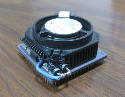
I just performed this modification on another POD83 CPU. This particular CPU couldn't even boot DOS at 100 MHz at stock voltage, however after the mod it ran everything beautifully - Win95, WinNT4, and GLQuake. I did not have another 6 A diode, so I connected two 3 A diodes in parallel which allows for a smaller profile compared to using a single 6 A diode. I was also able to perform the soldering without having to remove the heatsink, which saves a lot of hassle.

POD100_Mod_double_diode_1.jpg
Filename
POD100_Mod_double_diode_1.jpg
File size
97.36 KiB
Views
1808 views
File license
Fair use/fair dealing exception
POD100_Mod_double_diode_2.jpg
Filename
POD100_Mod_double_diode_2.jpg
File size
113.96 KiB
Views
1808 views
File license
Fair use/fair dealing exception

Plan your life wisely, you'll be dead before you know it.

Reply 39 of 89, by Zock

User metadata
Rank Newbie
Rank
Newbie

Hi would like to briefly with you thank reading for some time here in the forum and love.
Enjoyed my POD83 modded thanks to you and now he is running without problems.
Here are some pictures he has not become beautiful but it runs very stable. Write soon something more there but is very late 😀

Sorry for my English.

I still have a POD is then REV. 2.0 and will look better.

https://youtu.be/BNFbWrGq6p0

https://youtu.be/Lga48-v_azs

Attachments

  • 3.PNG
    Filename
    3.PNG
    File size
    1.56 MiB
    Views
    1738 views
    File license
    Fair use/fair dealing exception
  • 2.PNG
    Filename
    2.PNG
    File size
    1.69 MiB
    Views
    1738 views
    File license
    Fair use/fair dealing exception
  • 1.PNG
    Filename
    1.PNG
    File size
    1.09 MiB
    Views
    1738 views
    File license
    Fair use/fair dealing exception