Reply 20 of 23, by kalohimal
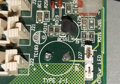
For your close up photo it is now quite clear that the 4 pins header is indeed for connecting external speaker. The BC55 is an NPN transistor, and the circuit is a typical common emitter switch, which sinks current to ground when it's turned on, like this:
The 2 "680" (68 ohms) resistors in parallel form Rs in the circuit, and there is no Rp (which is fine). These 2 resistors are in parallel to increase the current handling capability since each 0805 chip resistor is only 0.1W. The transistor output is connected to pin 1 of the 4 pins header, and is routed to the on board SP1 (the speaker that you broke) via the jumper to pin 2. If connecting an external magnetic/piezo speaker to pin 1 & 4 (pin 4 is Vcc) of J27 and you still have no sound, then there is probably something else that's broken. Leaving the broken pins in the holes on the motherboard do not affect anything, and the board won't "think" there is still a speaker.
To fix this, you'll probably need to find a friend who knows about electronics to help you troubleshoot. Basically you'll need to check the traces, the value of the resistors, the transistor, and the supply voltage with a multimeter. If an oscilloscope is available, it would be best to check the signal at both the base and collector of the transistor.
Slow down your CPU with CPUSPD for DOS retro gaming.

