Reply 40 of 54, by PCBONEZ
wrote:It's the same for tuned LC band stop filters, but that wasn't what they were using. More like a second order RLC filter, but split into two sections.
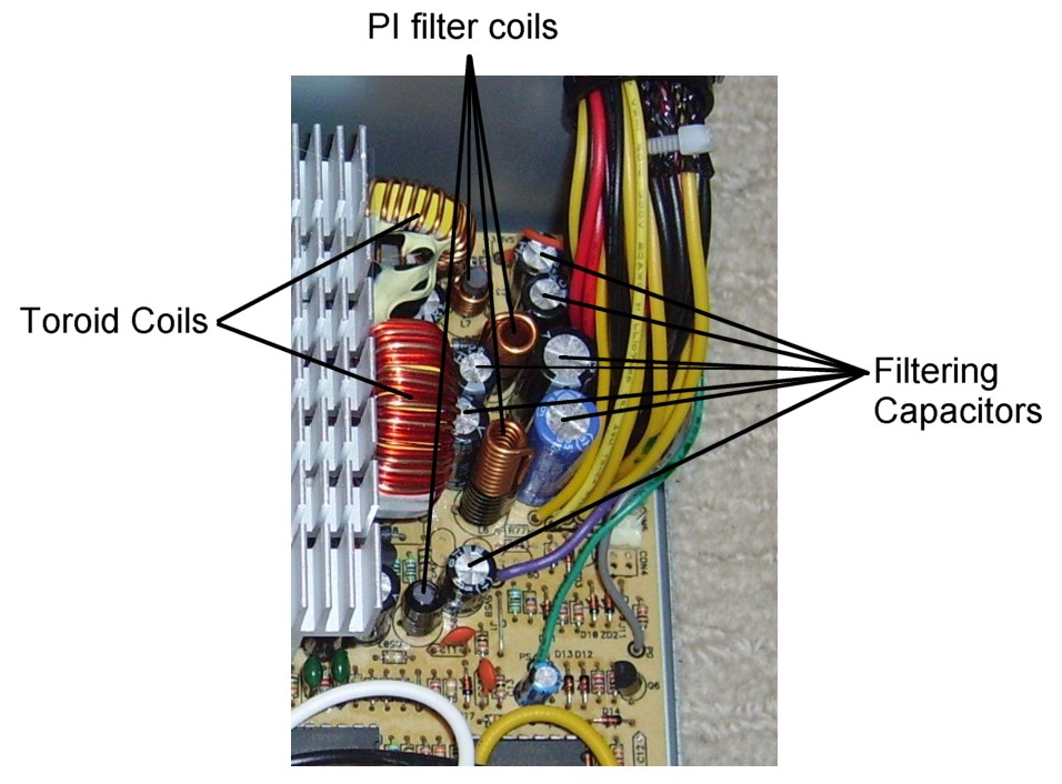
I was looking through my cache of old ATX schematics (trying to find typical values for the Pi filter inductors) and it suddenly occurred to me what this RLC configuration probably is.
Many PSUs have load resistors somewhere near the outputs. They are basically small "dummy loads".
They provide a minimum load on the given rail to ensure it regulates properly if the external load is too small.
Some PSUs without them will not stay running if they don't have an external load.
I believe their use is fading away because they reduce a PSU's overall efficiency.
.
Some schematics show them on every rail and others only on some rails.
Some show them before the series inductor and others after.
.
I also came across a few that have the load resistor but there is no filter inductor at all.
They count on just the toroidal transformer and a cap being enough filtering.
.
GRUMPY OLD FART - On Hiatus, sort'a
Mann-Made Global Warming. - We should be more concerned about the Intellectual Climate.
You can teach a man to fish and feed him for life, but if he can't handle sushi you must also teach him to cook.
