VOGONS


PGA132 rotator boards

Topic actions

Reply 80 of 116, by Sphere478

User metadata
Rank l33t++
Rank
l33t++
Ozzuneoj wrote on 2023-01-01, 06:55:
This may sound dumb, but would it be any benefit to have a design that made use of a couple different methods? For example, have […]
Show full quote

This may sound dumb, but would it be any benefit to have a design that made use of a couple different methods? For example, have the simplest (cheapest) PCB possible to cover as many pins as possible while using wire to relocate some pins that would require a far more complex PCB? Maybe even have ribbon cables twisted in the center to cover a couple rows? I know the idea of using twisted wire packed in epoxy\resin was suggestion earlier, but perhaps it is feasible if it this method isn't needed for every single pin. If it's a matter of looks, it could even be possible to encase the whole thing in a simple 3D printed frame or cartridge of sorts. You could route wires around the outside of the PCB that would otherwise not be possible without multiple layers, but it wouldn't be visible (ugly) if it were enclosed.

I have no experience with this stuff, I have just been intrigued by the "puzzle" you guys are working on and I can't shake that feeling that there must be some outside the box way to balance the cost of a complex PCB with ease of assembly.

Obviously a PCB (or multple PCBs) is the most elegant looking solution... but when getting into $60-$250 for these multi-layered boards, it's getting pretty pricey.

Again, you guys are obviously way more experienced at this than I could ever be, I just figured I'd toss some more ideas out there. 😀

There are a few ways to do this for sure.

All ideas welcome! :p

I think if any pcb is to be used, probably just do all of it in pcb.

It is an interesting thought though to split it into several pcbs.

As in, rotate one ring of pins on one pcb, then the others on another.

This may be possible, but will it do something we aren’t already doing. 🤔🤷‍♂️.

fascinating idea, but I don’t see the gain.

Gotta figure out what Feiopa is talking about.

But past that only way I see to make this better is to go 12 layer.

I feel like I found that elusive pattern to doing this that I was looking for.

I could take some of the redundant vias out (red and blue layers) but it seemed like it might be more uniform and even to leave them in, so I have.

Idk. I’m gonna give it another pass over, past that, next upload probably will be prototype time. But that may change depending on the ideas/changes feiopa has in mind that I am trying to understand.

Sphere's PCB projects.
-
Sphere’s socket 5/7 cpu collection.
-
SUCCESSFUL K6-2+ to K6-3+ Full Cache Enable Mod
-
Tyan S1564S to S1564D single to dual processor conversion (also s1563 and s1562)

Reply 81 of 116, by feipoa

User metadata
Rank l33t++
Rank
l33t++

Sorry for the delay. This is probably the worst time of the year for my free time.

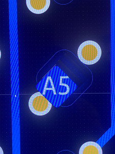
I can probably rephrase. Even with solder mask, I don't like how close the diamond shaped pads are to the adjacent via. They are, what, 100 um?

Since these diamond pads are all merely a direct short to a via next to it, why wouldn't we just solder the PGA pins to those vias and eliminate the diamond pads altogether? If the via is has too small of a surface area to solder the PGA pin to, then why not increase the amount of copper surrounding the via? Or even make the via a PGA through-hole? This is the crux of the misunderstanding.

Plan your life wisely, you'll be dead before you know it.

Reply 82 of 116, by Sphere478

User metadata
Rank l33t++
Rank
l33t++

One via connects to the pad above and one connects to the pad below. You may have already figured this out.

The clearance falls within design rules for the pcb. But for soldering I added the silk above them as a extra measure.

We might find if we removed the silk that these vias are actually burried under the mask quite well. But I suppose that depends on if jlc is having a good day or not 🤣 I think we noticed this on another project, which one , I forget. I think the first sxl2 prototype.

But anyway, you can see that offsetting the smd pga pad on the rotator pwould only work on one quadrant while misaligning others. As they aren’t all oriented the same way.

Also, this might result in less paths for routing.

I don’t see moving the pads helping. At worst it would mean totally starting over also to try.

Sphere's PCB projects.
-
Sphere’s socket 5/7 cpu collection.
-
SUCCESSFUL K6-2+ to K6-3+ Full Cache Enable Mod
-
Tyan S1564S to S1564D single to dual processor conversion (also s1563 and s1562)

Reply 83 of 116, by feipoa

User metadata
Rank l33t++
Rank
l33t++

Yes, some vias are burried well, others not. Do you know the distance between the SMD pad and the next via? Relying on silkscreen and surface coating as an insulator seems iffy.

It wouldn't be moving the solder pads, but turning the solder pads into thin through-holes that can accept solder. Was it not possible to make the solder pad and the via the same entity, similar to how the SXL2 prototype was designed with offset through-holes, but the holes on the rotator don't need to be so wide to fit a PGA pin into. We need just enough conductor on the via's surface to solder a PGA pin onto. I'm not sure what to call this, perhaps "thin PGA through-holes"?

For the "shim" layer, would you also be able to provide the same assembly but without the SMD pads? I would order both.

Plan your life wisely, you'll be dead before you know it.

Reply 84 of 116, by Sphere478

User metadata
Rank l33t++
Rank
l33t++

To do what you’re asking I would have to completely redo everything and it would be a offset socket I can’t make the via and the pad the same entity without shorting the upper and lower pad together unless I offset the upper and lower socket to either side

I do not share your concern over the vias shorting to the pads. Btw it is quite easy to test for this, the upper and lower pads will be shorted to one another.

Let me take a look at it here in a little while and see if there’s anything that I can do that doesn’t require a complete redesign to make those vias farther away from the pads Not that redesigning it is inherently a bad thing although it would really suck, been many hours of work. it’s just that any redesign is going to be physically larger if the goal is offsetting the sockets and I don’t see any gain in doing so.

something that will really help is we make this 12 layer and put ground planes in.

Sphere's PCB projects.
-
Sphere’s socket 5/7 cpu collection.
-
SUCCESSFUL K6-2+ to K6-3+ Full Cache Enable Mod
-
Tyan S1564S to S1564D single to dual processor conversion (also s1563 and s1562)

Reply 85 of 116, by feipoa

User metadata
Rank l33t++
Rank
l33t++

Having the bottom PGA pins offset from the top socket by 1.8 mm is not problematic from the stand-point of clearance around a motherboard's CPU socket. If this requires a whole rework, then nevermind. I'm mostly concerned with distance from that diamond shaped pad to the via and solder shorts, esp. with blind soldering. The supposed JLCPCB promotion deadline is approaching.

It was previously noted that Jan 5th was the deadline for this JLCPCB 6-8 layer promotion, but I'm having trouble finding this date published anywhere on the JLCPCB website. I see a January 5 2023 deadline for what looks like their previous promotion of $20 for 6-layer boards here: https://www.theengineeringknowledge.com/6-lay … on-pcbs-for-20/ But it is not clear to me if this deadline is for their new promotion as well.

EDIT: Here is the updated advert for the promotion: https://jlcpcb.com/help/newsdetail/42-6-8-Lay … ion-PCBs-for-$2

Last edited by feipoa on 2023-02-24, 05:24. Edited 1 time in total.

Plan your life wisely, you'll be dead before you know it.

Reply 86 of 116, by Sphere478

User metadata
Rank l33t++
Rank
l33t++

Feiopa, you are right. Sorry I didn’t see it sooner. These won’t work. The design rules checker didn’t catch the clearance issue. I assumed because there was no DRC that there was no problem. Let me see what I can do.

Last edited by Sphere478 on 2023-01-02, 06:33. Edited 1 time in total.

Sphere's PCB projects.
-
Sphere’s socket 5/7 cpu collection.
-
SUCCESSFUL K6-2+ to K6-3+ Full Cache Enable Mod
-
Tyan S1564S to S1564D single to dual processor conversion (also s1563 and s1562)

Reply 87 of 116, by Sphere478

User metadata
Rank l33t++
Rank
l33t++

edit old files don't use

Okay, update: I looked into moving the vias. that was gonna be a mess. so I tried a few things and came up with this:

image.jpg
Filename
image.jpg
File size
1.52 MiB
Views
744 views
File license
Public domain

I have solved the clearance issue by shrinking the diamond pad and the via rings.
Thoughts?

Filename
386 rotator and shim Beta .795 pads .6-.4 vias.zip
File size
130.17 KiB
Downloads
27 downloads
File license
Public domain

Here is a view looking under the silk

image.jpg
Filename
image.jpg
File size
1.85 MiB
Views
735 views
File license
Public domain

I looked it over again for errors. you might look also yourself. one thing noticed, but not yet corrected is
I will have to make another pass still to correct some more clearance issues that DRC didn't catch. the reason it didn't catch them is because unlike the other projects I didn't bother to give this one nets. At the time it seemed fine that they remain anonymous since everything was 1:1 Which was fine except that it caused this unexpected side effect. I have to enter a property window for each pad one by one for every single pad 264 times and type in the unique pad number and click save to add nets. And then possibly again 264 times for every via.. Now that I know it isn't checking for DRCs on the non netted stuff I can go through and manually check/adjust everything. or go back and add pad nets and let it tell me what to adjust. work, work, and more work.... :'(

Last edited by Sphere478 on 2023-01-04, 07:26. Edited 1 time in total.

Sphere's PCB projects.
-
Sphere’s socket 5/7 cpu collection.
-
SUCCESSFUL K6-2+ to K6-3+ Full Cache Enable Mod
-
Tyan S1564S to S1564D single to dual processor conversion (also s1563 and s1562)

Reply 89 of 116, by Sphere478

User metadata
Rank l33t++
Rank
l33t++
feipoa wrote on 2023-01-02, 11:35:

Would scooting the diamond shaped pads closer to the desired via be too time consuming?

Might be possible. But it isn’t going to move anything on the shim and would require an extra pad on the shim so there really is no point the solder is still going to be right where that pad is but now there is going to be even more of it. Doesn’t sound like a good idea.

I’m currently trying to get the board to the place that I thought it already was. Thanks to this DRC glitch 🤣.

I have been manually adding nets to every single pad and via and it really sucks. I worked on it for like 2 hours last night and still am not done I don’t know how many hours I have between these two projects but it’s a lot 🤣

This will make the DRC actually see everything and check the clearances. If the DRC likes it it should be good.

Sphere's PCB projects.
-
Sphere’s socket 5/7 cpu collection.
-
SUCCESSFUL K6-2+ to K6-3+ Full Cache Enable Mod
-
Tyan S1564S to S1564D single to dual processor conversion (also s1563 and s1562)

Reply 90 of 116, by feipoa

User metadata
Rank l33t++
Rank
l33t++

haha, learning takes time and life is learning. If it is wearing you down, come back to it some other time. There is no real deadline. Its unlikely you'd be able to meet the JLCPCB phantom deadline for the 180 degree board, which is the one I would actually use.

As for the shim, doesn't matter. I'm probably not going to use it. I'm more likely to use the shim which is just 132 pins straight through. Thus moving the diamond shaped pads would offer some help with respect to clearance.

Plan your life wisely, you'll be dead before you know it.

Reply 91 of 116, by Sphere478

User metadata
Rank l33t++
Rank
l33t++

Where do you want me to move them? The quadrants are all opposite orientations. Moving the pads will mess up the other quadrants.

Suggest drawing pics to show what you mean.

Do you see how the quadrants are oriented differently?

Sphere's PCB projects.
-
Sphere’s socket 5/7 cpu collection.
-
SUCCESSFUL K6-2+ to K6-3+ Full Cache Enable Mod
-
Tyan S1564S to S1564D single to dual processor conversion (also s1563 and s1562)

Reply 92 of 116, by Sphere478

User metadata
Rank l33t++
Rank
l33t++

Work on the drc fiasco is mostly done. There were only a hand full of actual clearance violations that were revealed by netting everything out. it will probably be 5 hours of work by time it is all back together. the clearace violations it found basically all consisted of 0.2mm allowed 0.1950 actual kind of bs. 🤣 fml.

the real problem was the via to pad clearance which was way too close, and is now long since fixed. I'm basically just making the drc checker happy at this point by filling in the remaining nets. it doesn't appear that any real errors remain at this point.

The drc is still going to be full of silk screen errors but that is fine because it clearances those at gerber generation. There will also be a bunch of "via only connected on one layer" errors. I can remove those vias but I kinda deicided maybe it was more even to keep them impedance wise. idk, they aren't hurting anything. If we take this 12 layer, I might need some of them.

Sphere's PCB projects.
-
Sphere’s socket 5/7 cpu collection.
-
SUCCESSFUL K6-2+ to K6-3+ Full Cache Enable Mod
-
Tyan S1564S to S1564D single to dual processor conversion (also s1563 and s1562)

Reply 93 of 116, by Sphere478

User metadata
Rank l33t++
Rank
l33t++

Okay, the CW 90* version is ready for your perusal.

before I upload it, do you want ground layers? (12 layer) or stick to 6 layer?

I think the best way to do this is with ground layers. but I understand the cost factor.

Sphere's PCB projects.
-
Sphere’s socket 5/7 cpu collection.
-
SUCCESSFUL K6-2+ to K6-3+ Full Cache Enable Mod
-
Tyan S1564S to S1564D single to dual processor conversion (also s1563 and s1562)

Reply 94 of 116, by feipoa

User metadata
Rank l33t++
Rank
l33t++

I don't think there would be any point in 10- or 12-layer. The cost is prohibitive. I predict that there wouldn't be any interest from anyone at $200+ for an order. 8-layer is max. It will be interesting to see if JLCPCB keeps $2 for 6 and 8 layer. If there was a hard deadline, why can't I find it? Department stores always make their sale deadlines obvious, because without a deadline, people will put off buying, and there is a fraction of people who won't buy it if they think its always available at the sale price.

There is no simple means to move the diamond pads, something like this, or to turn that vias into the diamond pad?

diamonds.jpg
Filename
diamonds.jpg
File size
1.15 MiB
Views
644 views
File license
CC-BY-4.0

I thought these PCB design programs had more automated ability to them. Is it just an issue with KiCAD as a program? Or perhaps this feature is there, but named in a way way that it is hard to find/use? Seems like an awful lot of manual, one-by-one placement here.

Plan your life wisely, you'll be dead before you know it.

Reply 95 of 116, by feipoa

User metadata
Rank l33t++
Rank
l33t++

By the way, I think the feeling of fire on the derrière can now be extinguished; there is no January 5th deadline as mentioned elsewhere. Here is my chat log with JLCPCB.

feipoa: For size under 5cm x 5 cm, is the price for 6- and 8-layer always going to be $2? Or is offer only valid until Jan 5th?

agent: yes, currently we don't know when it will be end. it should be very long

feipoa: Will there be a message on the website saying when the offer will end? Maybe at the end of January?

agent: yes, if it will be end, we will show the information in advance
but normally, it should not end shortly

Plan your life wisely, you'll be dead before you know it.

Reply 96 of 116, by Sphere478

User metadata
Rank l33t++
Rank
l33t++

Who knows if they even know themselves 🤣

feipoa wrote on 2023-01-03, 09:19:
I don't think there would be any point in 10- or 12-layer. The cost is prohibitive. I predict that there wouldn't be any interes […]
Show full quote

I don't think there would be any point in 10- or 12-layer. The cost is prohibitive. I predict that there wouldn't be any interest from anyone at $200+ for an order. 8-layer is max. It will be interesting to see if JLCPCB keeps $2 for 6 and 8 layer. If there was a hard deadline, why can't I find it? Department stores always make their sale deadlines obvious, because without a deadline, people will put off buying, and there is a fraction of people who won't buy it if they think its always available at the sale price.

There is no simple means to move the diamond pads, something like this, or to turn that vias into the diamond pad?
diamonds.jpg

I thought these PCB design programs had more automated ability to them. Is it just an issue with KiCAD as a program? Or perhaps this feature is there, but named in a way way that it is hard to find/use? Seems like an awful lot of manual, one-by-one placement here.

There are some features of the program that I am still unfamiliar with. But it doesn’t seem like there was a way to avoid this work if I wanted nets. The alternative would have been to manually check. Constructing a schematic beforehand would have helped but been a equal or greater amount of work. Possible I’m missing something here. But it is done now. Long way or short way, it’s done. Lol

I can move the pads yes

But that will misalign them from the socket you are going to solder on. The quadrants will move in different directions.

And the shim holes will still be located exactly where they are now. So I will have to add pads to the shim to move it back over

It doesn’t seem to be a good idea..?

In any case the clearances are all now within limits between the nets.

Sphere's PCB projects.
-
Sphere’s socket 5/7 cpu collection.
-
SUCCESSFUL K6-2+ to K6-3+ Full Cache Enable Mod
-
Tyan S1564S to S1564D single to dual processor conversion (also s1563 and s1562)

Reply 97 of 116, by Sphere478

User metadata
Rank l33t++
Rank
l33t++

Blue: aligned with LIF socket

Red: shifted onto destination via. No longer able to mate with LIF socket

Attachments

  • image.jpg
    Filename
    image.jpg
    File size
    1.6 MiB
    Views
    610 views
    File license
    Public domain

Sphere's PCB projects.
-
Sphere’s socket 5/7 cpu collection.
-
SUCCESSFUL K6-2+ to K6-3+ Full Cache Enable Mod
-
Tyan S1564S to S1564D single to dual processor conversion (also s1563 and s1562)

Reply 98 of 116, by feipoa

User metadata
Rank l33t++
Rank
l33t++

OK, if moving the diamond shaped pads makes the unit not align with the standard PGA-132, and would require a whole redesign, then nevermind that. Visually, it should be that nudging all the diamond shaped pads over in the exact same direction by the exact same distance should still match a PGA-132 footprint. However, as you've shown, it looks like not all the pads are offset from the via in the same direction! My mistake for not catching this. Trying to look at this with 3 kids home 24/7 during Winter break does not work well for me.

If you've met the clearance requirement, I'm willing to try it out for $2. In general, I think an offset board like the SXL2 may be a safer approach for this type of blind soldering, which I've not done before. I'm guessing the problem you ran into with the offset board was that the through-hole vias were too large and there wasn't enough space to route the traces? But if you made smaller vias one in the same with solder pads, it should work since the existing design works. Just everything needs to be nudged around manually, apparently quite a bit.

For the shim board, would you be able to make a shim board with only through-holes for the PGA pins, for which these holes align with the diamond pads on the rotator board? I want to use it as an alignment and support mechanism.

Plan your life wisely, you'll be dead before you know it.

Reply 99 of 116, by Sphere478

User metadata
Rank l33t++
Rank
l33t++

The shim

It can have pads and holes the same size as the diamond pads (though jlc may turn them into circles, we will have to see.)

Or it can be just pcb only with drill holes. No metal.

Which do you want?

Rotator using thru hole design:

It might be possible to do a offset thru hole. I don’t find it as elegant in this case though. And it would definitely be a full redesign. Not really worth it imho.

It would be even more cramped on the inner layers with the larger vias(now being larger plated thru holes for pins) also physically larger obviously.

The only thing we can do better I think would be more layers. Ground planes are easy.

I could go 8 layer and spread out the doubled up traces. That might help. But going 8 layer to add ground doesn’t make a whole lot of sense. We would want more like 12 layers.

I think this 6 layer smd design is the best of cheap, organized, and compact.

It’s not great for signal interference though.

I don’t think there is going to be a 180* version.

Here is why: It will have to have a high layer count or a bunch of uneven random spaghetti traces everywhere like shown earlier in thread.

It makes sense to simply try and bga stack this. It will give more distance between traces and cost will be low. Since the orders are already 5 per order you already get 2 180* versions per order.

To clarify. If I can get 180 routed on 8 layers *if* without doing a spaghetti design it is going to basically mean that every trace travels past twice as many traces and does so even more squeezed together than the 90* one

Where as if we bga stack it, every trace just travels twice as far (same distance as 180 design would) but only travels past half the traces as the 180 would. And all traces have more breathing room.

Bga stacking the 90* boards makes sense from a lot of angles. Doing it this way we could even use 2 90* 12 layer boards with ground planes. To make 180. Which would be best. But I’ll leave it 6 layer for now.

Making a 270* version of this isn’t too hard I can do that. I just have to re route, or figure out how to find the mirroring function. (It’s missing, and I can’t seem to find it outside of footprint editor) so may have to go el manual again. But basically we perfect this design, then I use this to make that.

Sphere's PCB projects.
-
Sphere’s socket 5/7 cpu collection.
-
SUCCESSFUL K6-2+ to K6-3+ Full Cache Enable Mod
-
Tyan S1564S to S1564D single to dual processor conversion (also s1563 and s1562)