VOGONS


Reply 40 of 51, by majestyk

User metadata
Rank Oldbie
Rank
Oldbie
Maxvintage871 wrote on 2024-05-02, 23:28:

...voltage to the tab of either Q2 or Q3 results in the 3.57v output of the transistor (same measured on both or 2.49 volts for the vcc2 transistor with mmx settings).

2.49V for the MMX (P55) setting is way too low. This should be 2.8 - 2.9V.
There´s definitely something wrong in the VRM circuit.

Reply 41 of 51, by Sphere478

User metadata
Rank l33t++
Rank
l33t++
majestyk wrote on 2024-05-07, 05:12:
Maxvintage871 wrote on 2024-05-02, 23:28:

...voltage to the tab of either Q2 or Q3 results in the 3.57v output of the transistor (same measured on both or 2.49 volts for the vcc2 transistor with mmx settings).

2.49V for the MMX (P55) setting is way too low. This should be 2.8 - 2.9V.
There´s definitely something wrong in the VRM circuit.

That is low for a board setup for p55, agreed.

But I would note that I have regularly ran MMX chips at that voltage (and lower) stable every time it seems at 233. So, p55c is usually stable at that voltage. Depending on clock speed and temp.

There are p55 mobiles specced at 2.45v btw.

Sphere's PCB projects.
-
Sphere’s socket 5/7 cpu collection.
-
SUCCESSFUL K6-2+ to K6-3+ Full Cache Enable Mod
-
Tyan S1564S to S1564D single to dual processor conversion (also s1563 and s1562)

Reply 42 of 51, by Nexxen

User metadata
Rank Oldbie
Rank
Oldbie
Sphere478 wrote on 2024-05-07, 16:09:
That is low for a board setup for p55, agreed. […]
Show full quote
majestyk wrote on 2024-05-07, 05:12:
Maxvintage871 wrote on 2024-05-02, 23:28:

...voltage to the tab of either Q2 or Q3 results in the 3.57v output of the transistor (same measured on both or 2.49 volts for the vcc2 transistor with mmx settings).

2.49V for the MMX (P55) setting is way too low. This should be 2.8 - 2.9V.
There´s definitely something wrong in the VRM circuit.

That is low for a board setup for p55, agreed.

But I would note that I have regularly ran MMX chips at that voltage (and lower) stable every time it seems at 233. So, p55c is usually stable at that voltage. Depending on clock speed and temp.

There are p55 mobiles specced at 2.45v btw.

It could indicate the inability to generate 2.8V and correct amperage.
Had that recently.
As I desoldered components V got up but no go.

PC#1 Pentium 233 MMX - 98SE
PC#2 PIII-1Ghz - 98SE/W2K

Reply 43 of 51, by Maxvintage871

User metadata
Rank Newbie
Rank
Newbie

Hello,
Address lines A0-A2 on the BIOS using the Post1A does produce what looks like very healthy signal, for only 3 seconds, then flatlines. It is a full 3 seconds on a cold start and less than 1 second on reset. There is more interesting signals on A0 and A1, A2 is a much lower frequency.

Please let me know if you think this leads you to another test? Maybe the CPU is signaled to halt or maybe the cpu is producing the hold signal

Thank you!

Attachments

Reply 44 of 51, by rasz_pl

User metadata
Rank l33t
Rank
l33t

This is great bad news, so the CPU crashes, somewhat explains glitchy postcard output. Now to "only" figure out if its the CPU or chipset making it crash.
Can you capture CPU Voltage rails during this 1 second just after reset to see if its messy, zoom in as much as you can. Optimally you could probe directly on the back of CPU socket. Would be interesting to see A0-1 and D0-7 CPU pins including their logic levels. Maybe its CPU Voltage regulator after all giving CPU so little power its barely able to drive Address bus, and not data bus at all so outputs are misinterpreted.

Open Source AT&T Globalyst/NCR/FIC 486-GAC-2 proprietary Cache Module reproduction

Reply 46 of 51, by Sphere478

User metadata
Rank l33t++
Rank
l33t++
rasz_pl wrote on 2024-05-09, 01:44:

This is great bad news, so the CPU crashes, somewhat explains glitchy postcard output. Now to "only" figure out if its the CPU or chipset making it crash.
Can you capture CPU Voltage rails during this 1 second just after reset to see if its messy, zoom in as much as you can. Optimally you could probe directly on the back of CPU socket. Would be interesting to see A0-1 and D0-7 CPU pins including their logic levels. Maybe its CPU Voltage regulator after all giving CPU so little power its barely able to drive Address bus, and not data bus at all so outputs are misinterpreted.

If it’s the power, a easy test is to just inject power from a bench top psu. Probably just leave onboard power active and just parallel it.

In my projects in sig I have some interposers which could be used to power separately. But not really needed to do the test.

Sphere's PCB projects.
-
Sphere’s socket 5/7 cpu collection.
-
SUCCESSFUL K6-2+ to K6-3+ Full Cache Enable Mod
-
Tyan S1564S to S1564D single to dual processor conversion (also s1563 and s1562)

Reply 47 of 51, by Maxvintage871

User metadata
Rank Newbie
Rank
Newbie

First, after staring at a pinout of socket 7, I have no idea where A0-A2 are located. Please let me know if I'm just missing those pins.
I can find A4 and above. I can also find D0 and above, which is what I tested below. The CPU is a standard Intel P133 and the jumper settings are set correctly where VCC2==Vcc3==3.6 volts.

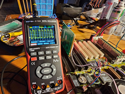
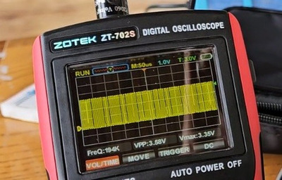
I measured D0 directly at the pin on the bottom of the board. I am using the Post1A bios. I have attached a video that you can see the D0 interesting data (this is 3 seconds after cold boot, but my video editing skills are lacking). At the 3 second mark, the voltage flatlines. I also included a higher res photo of the data line. It looks like we are getting pretty close to 3.35 vmax on D0 which would stand to mean that the voltage regulation is likely not the issue, right?

I was curious as to what the HOLD pin reported on start up. I took another measurement and in the same 3 second time we go from a lower frequency pattern to a higher frequency pattern. I attached that video as well.

Based on those 3.35 volt and the 3.6 volts I'm seeing, I don't think the cpu is running undervoltage. Any other ideas?

Attachments

Reply 48 of 51, by rasz_pl

User metadata
Rank l33t
Rank
l33t

>I was curious as to what the HOLD pin reported on start up. I took another measurement and in the same 3 second time we go from a lower frequency pattern to a higher frequency pattern. I attached that video as well.

>Hold Pin on Start Up.zip

pin E-15 is going high after 3 seconds?
At first its ~15 microseconds like standard ram refresh, except ram controller is not configured so what gives? is Intel chipset always running its refresh circuit no matter what?
After that screen/scope is aliasing so cant tell, but possibly at bus speed?

That is weird and beyond my knowledge. AFAIK nothing in a PC should be able to take over the bus on its own just after power on. Maybe someone else will have more ideas.

Garbage on post card + hold might be flaky southbridge. Have you looked (poked t with toothpick under magnification) at all the pins of two big Intel chipsets?

Open Source AT&T Globalyst/NCR/FIC 486-GAC-2 proprietary Cache Module reproduction

Reply 49 of 51, by Maxvintage871

User metadata
Rank Newbie
Rank
Newbie

I do have a microscope. I can check the pins on the chipset chips.
I did gently scrape a pick across the pins and didn't hear anything that would lead me to believe there were loose pins.
I will update as soon as I can check the pins.

Reply 50 of 51, by Maxvintage871

User metadata
Rank Newbie
Rank
Newbie

Hello all,
Thank you for suggesting to look in the microscope at the chipset. It turns out the large chipset chips are fine. I attached a picture of 75% of one of them just as an example, but nothing was out of ordinary there on either chip.

I was giving up in despair so I removed the CPU to put the board away into storage. That is when I remembered that putting the CPU into and out of the socket 7 was somewhat difficult. No pins are ever bent when changing the cpu, but the zif socket should have no resistance whatsoever. There was a bits and bolts youtube video that reminded me about damage to the socket: https://www.youtube.com/watch?v=EkRdjnAhA0w&t=341

So, I put the socket 7 under the scope and I think 2-3 pins are bent ( https://youtu.be/sTLeR0fGStQ ). However, I think they are just VCC3 pins so I don't know if missing connection on those pins would cause anything to be amiss. While reviewing the video I think a VCC2 pin might also be bent on the side nearest the socket arm.

I have no idea how to pull the socket 7 apart so I could inspect under the upper cover. I could try to replace the entire socket. Any suggestions?
Thanks!

Attachments

  • PICT0001.jpg
    Filename
    PICT0001.jpg
    File size
    570.97 KiB
    Views
    36 views
    File license
    Public domain

Reply 51 of 51, by Repo Man11

User metadata
Rank Oldbie
Rank
Oldbie

If you very carefully pry the edges of the socket's top cover (using something like a very small flat screwdriver), you can lift it off. I've done this on both Socket 478 and Socket 370 boards.

"I'd rather be rich than stupid" - Jack Handey