VOGONS


First post, by Old Thrashbarg

User metadata
Rank Oldbie
Rank
Oldbie

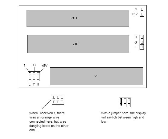
My 386 came with one of these in the case, but it wasn't hooked to anything. Setting the jumpers to display what I wanted was no problem, that part was wired the same as pretty much every other one.

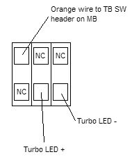
What I can't figure out, is how to actually hook it up to the motherboard. I have a vague idea of what needs to happen, but as far as where to plug things in to achieve that, I'm a bit lost. This one is set up differently from the ones I've previously encountered, and it doesn't help that most of the pins aren't marked. I have turbo switch and LED headers on the motherboard, two pins each.

So here's what I've got so far. When I got it, there was just the power hooked up to the header in the upper right, and a single orange wire hanging loose from one of the pins at the bottom left (as noted in my diagram). The functions of a couple of the pins are still unknown, one of 'em leads to one of two transistors on the board, and the other one goes somewhere I can't see. The functions are marked just as I traced 'em out. I also found that the display will not switch properly unless a couple of the pins are jumpered... though it might behave differently if that orange wire was hooked to something, I dunno.

Maybe I've just been staring at it for too long, but I can't get my head around it. All I want is to press the button, system changes mode and the display changes. How can I hook it up so that happens?

Attachments

  • untitled.jpg
    Filename
    untitled.jpg
    File size
    18.82 KiB
    Views
    1431 views
    File license
    Fair use/fair dealing exception

Reply 2 of 6, by ux-3

User metadata
Rank Oldbie
Rank
Oldbie

From turbo button two cables should emerge:
One goes to the board. The other goes to the orange wire connect. The Display is dumb about the board, it knows only about the switch.

Retro PC warning: The things you own end up owning you.

Reply 4 of 6, by Old Thrashbarg

User metadata
Rank Oldbie
Rank
Oldbie

There's only one 3-wire cable coming from the turbo button, and it's not possible that the orange wire just came loose from there either. If the orange wire were to go to the led header on the mainboard, then where would the LED plug in?

The way I'm thinking it, the turbo switch would hook to the H/G/L header on the display board, and then somewhere on that little 3x2 header should be a way to hook up a lead to the switch header on the motherboard, and possibly also the turbo LED as well. That just seems like the simplest way to hook it up...

Reply 6 of 6, by Old Thrashbarg

User metadata
Rank Oldbie
Rank
Oldbie

OK, after a bit more playing around with it, I may have figured it out. Now I just need to test whether it's actually switching the system speed. The display changes, and the LED goes on and off, so it's a start, anyhow.

Here's how I have it hooked up... only thing I don't get is how the switch would work with only one wire connected, since I don't know how the circuit actually operates...

EDIT: HM, it doesn't seem to be working properly... back to the drawing board, then.

Attachments

  • untitled2.jpg
    Filename
    untitled2.jpg
    File size
    5.62 KiB
    Views
    1347 views
    File license
    Fair use/fair dealing exception