VOGONS


First post, by tannerstevo

User metadata
Rank Member
Rank
Member

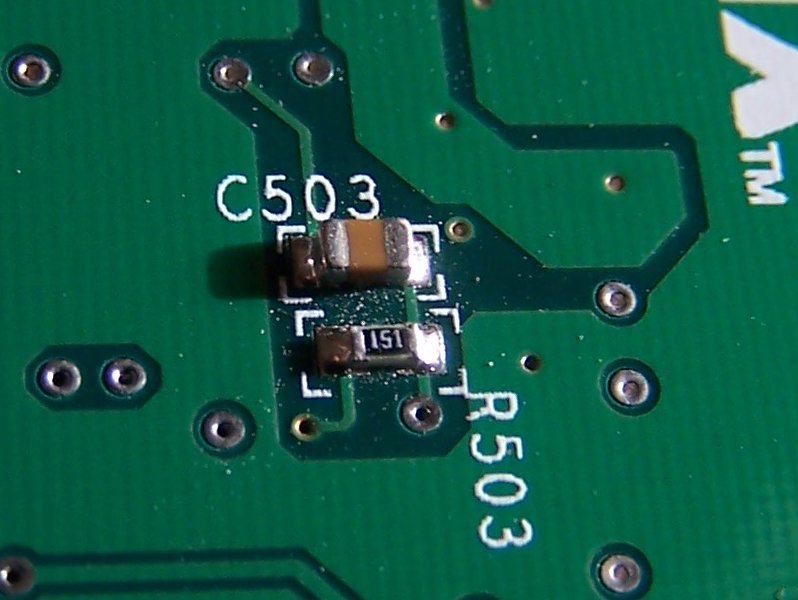
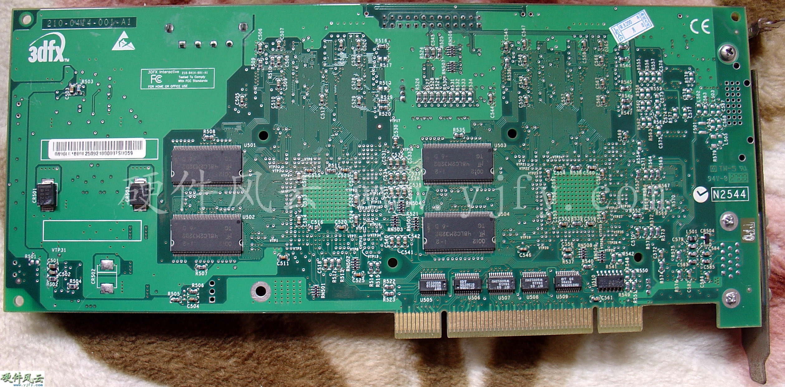
I have a voodoo 5 pci card that has no video. I was looking at it and noticed that at R503 it appears something was once there

th_IMG_0809.jpg

Does anyone here have one of these cards that they could check to see if there is supposed to be something there. I think that it should be a resistor. If so there should be a number on it. Any help would be appreciated.

Reply 1 of 10, by unmei220

User metadata
Rank Member
Rank
Member

Yes, as it says in the PCB, and also because the looks of the spot, there was a resistor there. Unfortunately I don't have a V5 anymore so I can't help you, but i'm sure someone will do.

These are the best images I could find. The first one has the back just like the one you have, unfortunately, I can't spot any number in the R503 resistor:
http://www.yjfy.com/images/oldhard/video/Vood … _PCI_2700_1.jpg
http://www.3dfx.ch/gallery/d/31237-1/3dfx+Voo … 1+2900+Back.JPG

This one is not the same, it's completely different, but you can clearly spot the numbers over many resistors, including R503, which is in a different position:
http://3dfx.weppel.nl/3dfxpics/3dfx%20Voodoo% … %20Back%202.jpg

Maybe they help you someway meanwhile.

Reply 4 of 10, by Jorpho

User metadata
Rank l33t++
Rank
l33t++

So how do you fix something like that, exactly?

For months now I've had a broken DS Lite sitting around. The repair, which consists of replacing a blown surface-mount fuse (similar to this resistor), is well-documented, but I've never tried to solder something that tiny before, and I don't know how or where to learn, or even where to find someone to do the job for cheap.

Reply 5 of 10, by Machine_1760

User metadata
Rank Newbie
Rank
Newbie

you'll need: solder wick/braid, a very fine soldering iron tip, some very fine needle nose pliers or surgical forceps to hold the lil' bastard and a very steady hand. If you can find any then leaded solder will work best as it'll reflow better.

1. use the braid and soldering iron to clean the plated pads on the PCB surface on each end of the component location
2. use the soldering iron to carefully apply a bead of solder to each plated connector and wait for it to cool
3 hold the component so it rests upon the solder beads and use the soldering iron to reflow either end of the component to the PCB.

Simple!

Reply 6 of 10, by Jorpho

User metadata
Rank l33t++
Rank
l33t++

It's the "steady hand" part that bothers me. Seems like something that requires practice.

Another question: I can see in this case you would apparently need a 150Ω resistor. But, assuming there's space, do you really need to use an SMD resistor, or will an ordinary resistor with big gangly leads do just as well, especially considering it wouldn't be going into an especially-cramped space?

Machine_1760 wrote:

2. use the soldering iron to carefully apply a bead of solder to each plated connector and wait for it to cool

Do you mean the "plated connectors" on the component or on the board..?

Reply 7 of 10, by tannerstevo

User metadata
Rank Member
Rank
Member
Jorpho wrote:

Seems like something that requires practice.

For me it also requires a magnifying glass.
Unfortunately, it did not fix my card. guess I will put it away for a while.

Reply 8 of 10, by Machine_1760

User metadata
Rank Newbie
Rank
Newbie

Good question! and the honest answer is that I don't know for sure! I see no reason that a regular through hole resistor wouldn't work although you may cause more damage to the board later on if the solder joints are weak or the resistor was torn off accidentally.

The solder beads should be applied to the pads on the board first so you only heat the component once during repair.

The steady hand part was slightly tongue in cheek! when you apply the solder beads the solder will only stick to the PCB pads so there's no need to be horribly accurate. The same applies to the component, when the first end is 'fixed' it'll stay there while you reflow the other end. Just make sure you're gentle and relatively quick with the soldering iron.

Reply 10 of 10, by Ace

User metadata
Rank Oldbie
Rank
Oldbie
Jorpho wrote:

Another question: I can see in this case you would apparently need a 150Ω resistor. But, assuming there's space, do you really need to use an SMD resistor, or will an ordinary resistor with big gangly leads do just as well, especially considering it wouldn't be going into an especially-cramped space?

I've replaced several surface-mounted resistors with plain old resistors and have never had a single problem other than ripping a few traces here and there. Here's my suggestion if you're going to use a standard resistor rather than a surface-mount resistor:

1) Solder 2 pieces of IDE ribbon cable, one on each end of the solder spot
2) Solder the leads on the resistor to the other ends of each wire

This will make it less likely for you to rip a trace off the PCB.

And yes, that is a 150ohm resistor.