VOGONS


PS/2 6 pin cable - are they hard to find?

Topic actions

Reply 20 of 79, by Markk

User metadata
Rank Oldbie
Rank
Oldbie

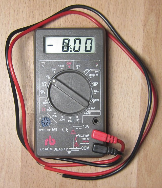
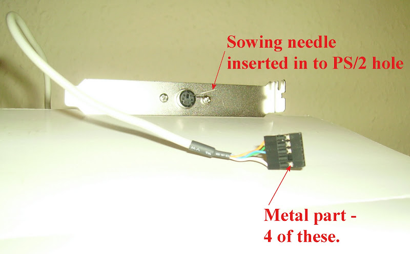
I have the same multimeter! (almost... mine is identical but with a different maker label). Yes, you have to switch on the board to measure. I would recommend to take a molex power connector and plug the black wire of the mm into one of the two middle holes of the connector that are leading to a black ground wire from the psu. Then you can touch each one of the pins on the ps/2 header with the red cable of the mm, and when you read around 5v on the screen, then you know which pin is that. After that, you do the opposite. Plug the red wire to 5v on a molex, and with the black touch the other pins (be careful. Avoid to touch those that you found that are the 5v ones), and that way you can find which of the pins are ground.

Reply 21 of 79, by 5u3

User metadata
Rank Oldbie
Rank
Oldbie
Markk wrote:

I have the same multimeter! (almost... mine is identical but with a different maker label)

Seconded. 😀

multimeter.jpg

This is the first multimeter I ever bought, and that was at least 15 years ago! 😳
The display is slightly broken and the probes are long gone, but it still works.
The "rb" stands for "Radiobastler", the name of a small electronics store chain which doesn't exist any more.

Reply 23 of 79, by Yushatak

User metadata
Rank Member
Rank
Member

I've got several mobos that have these headers. As far as I know, the 5-pins-in-a-row headers (your first eBay link) are standardized among themselves. I'd go with that bracket and try my luck - it will likely work.

I've also got that same multimeter, but mine's red and also has a different brand. Seems to be one of those "everybody buy these for cheap, ship them to America, and rebrand them!" deals.

Reply 24 of 79, by retro games 100

User metadata
Rank l33t
Rank
l33t

Thanks a lot for the info! 😁 Before trying the multimeter, I attached the PS/2 5 pin header cable to the mobo's PS/2 header pins, and I tried this using both "directions" for this plug. Unfortunately, my PS/2 mouse was not detected by Windows 98.

I tried the multimeter, and successfully double-checked the pin location of the mobo's PS/2 5V pin. It matches up with the diagram provided by Keropi, and it's pin number 4. I did not double-check the pin location of Ground, which is pin number 3. I didn't want to risk accidently brushing the black probe against pin number 4, which is 5V. Say if I accidentally did that. What would happen?

Now, I need to understand what the 4 wires do which form the PS/2 cable. How do I do that please? Do I determine their function, by looking at their colors? Or do I use a multimeter? I tried using the red probe, but I got no reading when I pressed the red probe's pointer up against the tiny metal connectors inside the PS/2 cable socket, where you can see the ends of these 4 small coloured wires.

Another thing: I cannot see how I can carefully pull out these 4 wires, away from the PS/2 cable plug. Thanks a lot for any more help! I feel as if I'm half way there to solving this problem, and I've learnt a bit about the MM, which is great! 😀

Reply 25 of 79, by Tetrium

User metadata
Rank l33t++
Rank
l33t++
TheMAN wrote:

is that a play on name for "radio shack"? 🤣

Lol, could be, but I don't think so. Translated it means something like "Radio Hobby-ing" or something 😜

On topic:The fact that these pin headers aren't standard is a nuisance, it's the same for USB headers. I have a small box full of those cables (pulled from orphaned systems on the streets years ago) and never paid any attention to what I removed the cables from. Back then I didn't remove "all" motherboards from the cases I found. Otherwise I would've had a pile of a couple meters of those VX boards LoL!

Reply 26 of 79, by Markk

User metadata
Rank Oldbie
Rank
Oldbie

RG100 here's the pinout for the ps2 mouse connector : http://pinouts.ru/Inputs/PS2Mouse_pinout.shtml

However, have in mind that some boards may require to enable ps/2 mouse from the bios, or even in some cases you have to place a jumper for that.

Reply 27 of 79, by retro games 100

User metadata
Rank l33t
Rank
l33t
Markk wrote:

RG100 here's the pinout for the ps2 mouse connector : http://pinouts.ru/Inputs/PS2Mouse_pinout.shtml

Thanks a lot. This pinout information matches up exactly with the mobo's pinout diagram, for its onboard PS/2 header. Unfortunately, I don't understand how I can use this knowledge to determine what "function" each of the 4 wires on the PS/2 cable does. The 4 wires in this 5 socket cable are:

1) White
2) No wire
3) Blue
4) Green
5) Orange

I am guessing that this order is from pin 1 to 5, although it could be in the reverse order! How do I understand what colour wire corresponds to which PS/2 pinout function? Thanks a lot for any help!

Edit: I have tried the 5 socket PS/2 cable plugged on to the mobo's 6 pin PS/2 header. I plugged it in, as seen in the pin number sequence above. I tried 3 mice, and none could be detected. There are no PS/2 jumpers on the mobo, and no mention of a PS/2 mouse in the BIOS settings! Strange. I read the manual, and although the manual is not exact for the PCB board revision, it doesn't mention anything about a BIOS PS/2 mouse option to Enable/Disable. I wonder if I need a BIOS upgrade? I have a P5BV3+ revision B3 board.

Reply 28 of 79, by Tetrium

User metadata
Rank l33t++
Rank
l33t++
retro games 100 wrote:
Thanks a lot. This pinout information matches up exactly with the mobo's pinout diagram, for its onboard PS/2 header. Unfortun […]
Show full quote
Markk wrote:

RG100 here's the pinout for the ps2 mouse connector : http://pinouts.ru/Inputs/PS2Mouse_pinout.shtml

Thanks a lot. This pinout information matches up exactly with the mobo's pinout diagram, for its onboard PS/2 header. Unfortunately, I don't understand how I can use this knowledge to determine what "function" each of the 4 wires on the PS/2 cable does. The 4 wires in this 5 socket cable are:

1) White
2) No wire
3) Blue
4) Green
5) Orange

I am guessing that this order is from pin 1 to 5, although it could be in the reverse order! How do I understand what colour wire corresponds to which PS/2 pinout function? Thanks a lot for any help!

Edit: I have tried the 5 socket PS/2 cable plugged on to the mobo's 6 pin PS/2 header. I plugged it in, as seen in the pin number sequence above. I tried 3 mice, and none could be detected. There are no PS/2 jumpers on the mobo, and no mention of a PS/2 mouse in the BIOS settings! Strange. I read the manual, and although the manual is not exact for the PCB board revision, it doesn't mention anything about a BIOS PS/2 mouse option to Enable/Disable. I wonder if I need a BIOS upgrade? I have a P5BV3+ revision B3 board.

I learned on vintage-computer.com there are KVM switches that you can connect a PS/2 mouse to and connect the KVM to the motherboards serial port. The KVM switch should emulate the serial mouse and you can use a PS/2 mouse.

It's in the thread where I ask about USB cards in 486 motherboards, maybe it's of some help?

Reply 29 of 79, by h-a-l-9000

User metadata
Rank DOSBox Author
Rank
DOSBox Author

Are you aware that you can fry your mice if the supply voltage pins are switched?

Use the continuity test of your multimeter to check which wire goes where. Put a piece of wire in the PS2 pinhole and hold a probe to it.

1+1=10

Reply 30 of 79, by retro games 100

User metadata
Rank l33t
Rank
l33t
h-a-l-9000 wrote:

Are you aware that you can fry your mice if the supply voltage pins are switched?

Use the continuity test of your multimeter to check which wire goes where. Put a piece of wire in the PS2 pinhole and hold a probe to it.

I am not aware of this. However, after reading your advice, I am now. 😀

When you say "... and hold a probe to it". Do I put the black probe in to one of the PSU's middle molex sockets, and then switch on the PSU power, and then use the red probe to test the 4 wires inside the PS/2 cable for continuity? Thanks a lot for any advice.

Reply 31 of 79, by h-a-l-9000

User metadata
Rank DOSBox Author
Rank
DOSBox Author

You do this with the PS2 cable not plugged in.

Switch your multimeter to continuity test (the symbol with the diode, 5:30 o'clock). It should display something like '1 ' with the probes not connected. Now hold the probes together, it should be close to '000' and emit sound as it looks.

Now hold one probe to the metal part of a contact of the board side of the cable that can be touched from the side, the other to the wire that sticks in a pinhole. If its '000' then the wire matches the pinhole. If not, try all other holes or contacts.

1+1=10

Reply 32 of 79, by retro games 100

User metadata
Rank l33t
Rank
l33t

I need to double-check that I understand exactly what you mean. I think you want me to do this -

* Select the continuity option on the MM. It's at 5:30. I have double-checked this on the net, and I've got the MM's dial set correctly.

* I test continuity by pressing both probes together. I hear a beep. Continuity testing can now begin.

* Switch on the power to the mobo, so that the PC is running. Do I need to do this?

* Press one probe (and it does not matter what the colour is) on to one tiny wire inside the PS/2 cable plug (which is not plugged in to the mobo). This can be done using a piece of wire pushed inside the PS/2 cable's plug. Press the other probe on to one of the mobo's 6 PS/2 pin headers. Try the mobo's PS/2 pin header number 1, then 2, then 3...up to pin 6.

Is this correct? Thanks a lot. BTW, I have tried the sequence of events above, but *without* switching on the power to the mobo, and I did not hear any beep sound, when I tested one wire inside the PS/2 cable plug in conjunction with pressing the other probe against all 6 PS/2 header pins on the mobo. Thanks.

Reply 34 of 79, by retro games 100

User metadata
Rank l33t
Rank
l33t
h-a-l-9000 wrote:

> * I test continuity by pressing both probes together. I hear a beep. Continuity testing can now begin.

Does it beep or not? What's on the display?

When I do this very simple continuity test by pressing both probes together, I hear a continuous beep. Sometimes, it sounds a bit "scratchy". Before pressing the probes together the display says 1. After pressing the probes together and I can hear the continuous beep, the display goes "a bit mad", then settles down and displays 004, then 003, then 002, then 001, and then stops on 000. The beep sound can still be heard, and the display still shows 000.

Reply 35 of 79, by h-a-l-9000

User metadata
Rank DOSBox Author
Rank
DOSBox Author

Ok, working as intended.

You do not need to do anything with the mainboard as it is not connected to the cable. At this time the world is "reduced" to the multimeter and the PS2 plug.

I hope you used a piece of wire that is not isolated. Also keep in mind that only four of the six pinholes of the PS2 connector are connected to the other side.

1+1=10

Reply 37 of 79, by retro games 100

User metadata
Rank l33t
Rank
l33t

OK, thanks a lot for your help. I must double-check what you have said. I think you want me to do this -

Put a piece of metal in to one of the 6 socket holes on the PS/2 socket, on the "bracket area". In the photo, I am using a sowing needle. Is this OK? I press a probe on to the sowing needle. I also press the other probe against the small metal part on the plug. On the photo, the small metal part is shown exactly where the red arrow is. I then move this probe from that metal part, to the next metal part, until all 4 metal parts have been tested. After these 4 tests, I remove the sowing needle from the PS/2 hole, and replace it inside another hole. That needs to be done 6 times, because there are 6 holes on the PS/2 socket, on the "bracket area".

Is the above correct? If it is correct, then what am I looking for, when these tests are being done? If the unit beeps at me, how can I understand if the beep means "mouse data" or "Ground" or "5V" or "mouse clock"? Thanks a lot.

Edit: I spelt sowing needle wrong. It's sewing. RG100 doesn't do a lot of sewing, you understand. 🤣

ps2_b.jpg

Last edited by retro games 100 on 2011-03-02, 22:52. Edited 1 time in total.

Reply 38 of 79, by TheMAN

User metadata
Rank Oldbie
Rank
Oldbie

all you will know is which pin corresponds to which wire.. the pin on the ps/2 connector are specific of course, which you can easily find out which pin does what.... as for how the wires are arranged on the motherboard end, you are on your own there.... you may need to move them around to match what the motherboard has... since you don't have a manual, you'll have to determine this yourself by reading the voltages off the meter while the board is powered up I think

so far, all your testing as done is determined which end goes where on the connector/wires..... like pin 1 corresponds to yellow wire, etc (hypothetically)

Reply 39 of 79, by h-a-l-9000

User metadata
Rank DOSBox Author
Rank
DOSBox Author

Yes, that's correct.

Look at the pinout: http://pinouts.ru/Inputs/PS2Mouse_pinout.shtml
The hole the needle is in is pin #5 (see the little picture top left on that page).
The table below says pin #5 is 'clock'.

1+1=10