VOGONS


The Socket 3 POD83 and overclocking

Topic actions

First post, by Tetrium

User metadata
Rank l33t++
Rank
l33t++

So I've been thinking...

After all the overclocking experiments we've come to the conclusion that one of the disadvantages of overclocking the POD83 is the inability to raile it's voltage. As Socket 3 boards generally only supply voltages between 3.3v and 5v and the POD83 is supposed to be run @ 5v, which it undervolts down to 3.3v, there is basically no headroom for tweaking the CPU voltage here (except maybe for underclocking).

This is because the POD83 uses an onboard (or on-chip) voltage regulator.

I've tried to take some pics of the regulator but this is hard as most of the regulator is being obscured by the glued-on heatsink.
Pics:
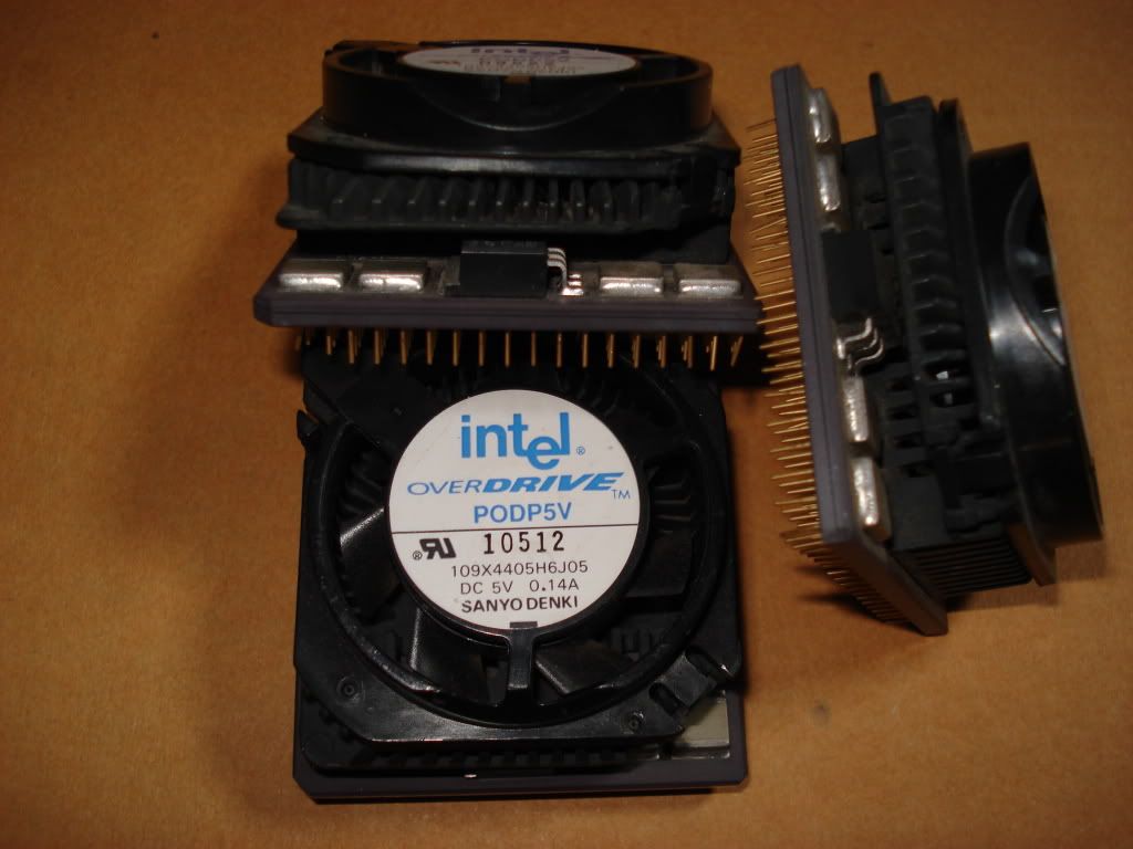
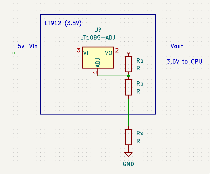
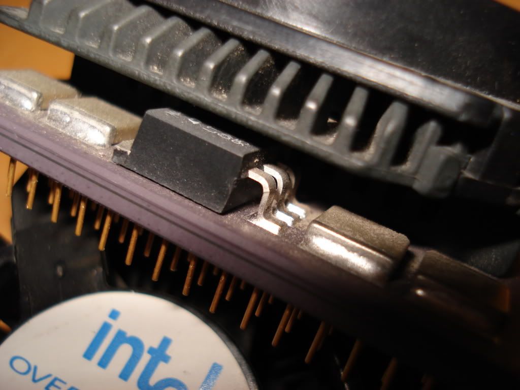
Overview pic of a couple POD83's. You can see the voltage regulator in between the ceramic and the heatsink (It's the black boxy thing in between the 4 smaller grey boxy thingies).
th_DSC00664.jpg

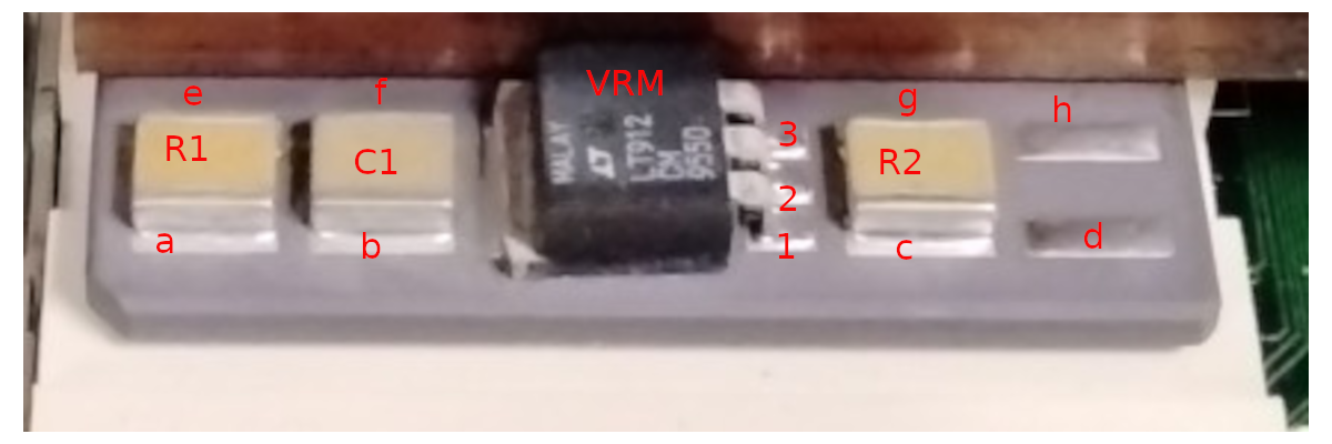
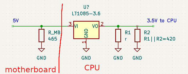
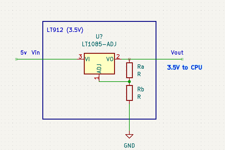
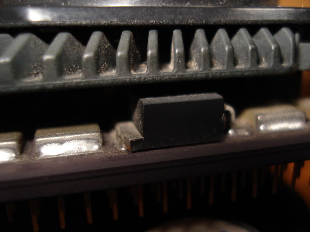
Closeup of the voltage regulator, from one side and from the other side.

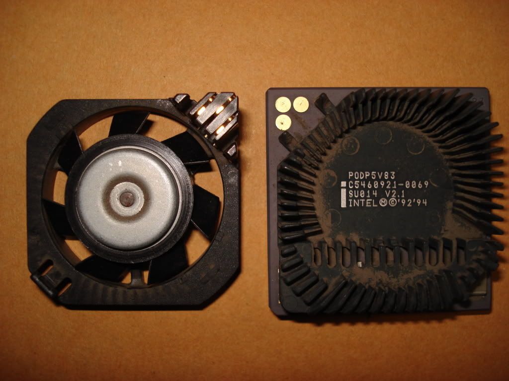
Another thing that needs to be kept in mind is the fan mounted on the heatsink. It's a 5v fan powered directly from the CPU via the CPU socket.
It receives it's power from the 3 golden dots in the corner of the ceramic package (pic of the 3 golden dots here).

When the fan is removed from the 3 golden dots, the internal multiplier is reduced from 2.5x to 1x, creating another hurdle for overclocking as the tiny integrated fan can't be replaced by a generic fan without the POD83 doing it's underclocking.

The 2 thoughts I've been having are these:
1)What if the onboard voltage regulator were to be neutralised? And how could one accomplish this.
Would it be possible to simply "snip" the 3 metal legs of the voltage regulator? Or would it be required to do some extra soldering or some extra painting with conductive paint?
2)After having read the Intel datasheet (which is here) theres very little info about how the little Intel 5v fan is wired.
It uses 3 wires, of which 2 are probably for providing power (one ground and 1 5v, as per requirement of the fan) and 1 may be somekind of counter?
The question is: Which one of the 3 golden dots are for the counter and how could it be possible to "fool" the POD83 into thinking the fan hasn't been removed when it is?
Would it be possible to use a generic 3-pin fan, put it on 5v (just in case the "counter" wire of the generic fan starts sending 12v signals back to the 5v (regulated down to 3.3v?) of the POD83) and then somehow connect it to the correct golden dot?

I wasn't able to see the text written on the voltage regulator, but I have a broken Intel Overdrive (non-Pentium) I'm willing to destroy in order to see what voltage regulator is being used (should be roughly similar as it serves the same function that the POD83 regulator has, lowering the voltage from 5v to 3.3v).

Any suggestion, ideas, ...input?

Whats missing in your collections?
My retro rigs (old topic)
Interesting Vogons threads (links to Vogonswiki)
Report spammers here!

Reply 1 of 30, by Dant

User metadata
Rank Member
Rank
Member

I'm not experienced with Much Pre-Pentium 2 era hardware, but...

I highly doubt that it would be wise to overide the voltage regulator, looking around some it would seem the overdrive is little more than an adapted P54C (Socket 5 vanilla Pentium) If they take 5V on an overclock no problem then the overdrive will in theory as well. Of course this is all assuming the voltage regulator can be bypassed...

As for the fan.. easy enough. Just take the fan off, solder some wire to the pinout and mount the fan somewhere else in the case. While using your own cooling setup on the CPU.

Reply 2 of 30, by Old Thrashbarg

User metadata
Rank Oldbie
Rank
Oldbie

Bypassing the voltage regulator entirely seems like a very bad idea... but it might be possible to rig up an adjustable regulator in its place (assuming it's not already an adjustable regulator on there... all I can make out is that it's some sort of LT-series chip).

As far as the fan wiring, well, you should be able to pretty easily figure out the 5V and ground just with a multimeter, so the question just comes down to how the sensor works. If it's just a basic life sensor, i.e, "fan is running" or "fan is not running" it might be fairly easy to get around. If it's a tachometer sensor it could get a bit more complicated, since it would probably be expecting a certain RPM range.

Reply 4 of 30, by Tetrium

User metadata
Rank l33t++
Rank
l33t++

Thanks for the replies!

I know next to nothing about voltage regulators (I'm not an electronics engineer or anything like that), but I did manage to pop off the heatsink of that DX4 overdrive and will post a pic of the regulator later 7am here, still trying to wake up). Maybe someone else can make heads or takes out of it?

And this is more an experimental exercise, it would already start to get interesting if it can clock a wee bit higher

Whats missing in your collections?
My retro rigs (old topic)
Interesting Vogons threads (links to Vogonswiki)
Report spammers here!

Reply 5 of 30, by Mau1wurf1977

User metadata
Rank l33t++
Rank
l33t++
Tetrium wrote:

I know next to nothing about voltage regulators

There should be a part number on it. Google that and you should be able to find out everything about it.

A voltage regulator basically takes a higher voltage and outputs a lower one. The more current flows, the larger the regulator and the heatsink attached to it.

Reply 6 of 30, by feipoa

User metadata
Rank l33t++
Rank
l33t++

Not all regulators drop the voltage, there are also step-up regulators.

Anyway, it looks as if Tetrium is thinking to raise the voltage on this POD-83 a bit to increase stable yields when overclocking. He might be on to something here. Maybe if we can get the POD's to run at 3.8 V or 4.0 V, all, or most, of them will be stable at 100 MHz? Maybe if we are diligent enough, we can get one working at 125 MHz (50 x 2.5). To answer some of your questions,

Cutting the leads to the voltage regulator will probably mean you get 0 volts going to the CPU, so, bad idea!

For this particular regulator, it beleive it is set to step down a 5V voltage to 3.3V, internally. You can find out which pin on the regulator is the V,in and which is V,out by using a volt-meter to see which voltage is 5.0V and which is 3.3V. If you are really determined to run your POD at 5V internally, you'd only need to solder a wire from V,in to V,out.

If you want to be fancier about it, there are two options intel may have implemented. What are those other silver squares on the side of the regulator? If one of them is a resistor, see if one lead is connected to V,out, or to Ground. If so, it may be the resistor setting the regulation circuit's output voltage. Measure the resistor's impedence with a multi-meter. Desolder it and put in place a potentiometer that has a resistence of +-50% of your measured resistor's impedence. Then tune the potentiometer and measure V,out. Does it change? [note, for these two options, you should have not wired V,out to V,in.]

If not, maybe you picked the wrong resistor? It might be that there are no accessable resistors. The resistor of interest might be part of the dye pattern (unlikely), or Intel put in place a fix voltage resistor, such that no matter what your V,in is, your V,out will always be the same. A voltage regulator of that style does not use external resistors, so the user cannot alter the output voltage. If that is the case, you can always change the regulator. Digikey has tonnes of fixed output regulators.

As for the fan lead, you can take the fan apart to see if there is any kind of encoder (emiter/detector) in there. If so, it is likely counting revolutiosn as, say, 1 pulse per revolution. It would be tough to beat that, unless you wanted to wire it to the tacometer of any other new fan you put on. But the Intel circuitry might be stupidider, you can try playing around with setting the tach input to always 5V and see if the chip drops the CPU rate.

The fan/heatsink seem pretty optimized and I wouldn't see any reason to change that combination.

I hope this helps. I think a few hours poking around and you'll have your answers.

Plan your life wisely, you'll be dead before you know it.

Reply 7 of 30, by Tetrium

User metadata
Rank l33t++
Rank
l33t++
feipoa wrote:
Not all regulators drop the voltage, there are also step-up regulators. […]
Show full quote

Not all regulators drop the voltage, there are also step-up regulators.

Anyway, it looks as if Tetrium is thinking to raise the voltage on this POD-83 a bit to increase stable yields when overclocking. He might be on to something here. Maybe if we can get the POD's to run at 3.8 V or 4.0 V, all, or most, of them will be stable at 100 MHz? Maybe if we are diligent enough, we can get one working at 125 MHz (50 x 2.5). To answer some of your questions,

Cutting the leads to the voltage regulator will probably mean you get 0 volts going to the CPU, so, bad idea!

For this particular regulator, it beleive it is set to step down a 5V voltage to 3.3V, internally. You can find out which pin on the regulator is the V,in and which is V,out by using a volt-meter to see which voltage is 5.0V and which is 3.3V. If you are really determined to run your POD at 5V internally, you'd only need to solder a wire from V,in to V,out.

If you want to be fancier about it, there are two options intel may have implemented. What are those other silver squares on the side of the regulator? If one of them is a resistor, see if one lead is connected to V,out, or to Ground. If so, it may be the resistor setting the regulation circuit's output voltage. Measure the resistor's impedence with a multi-meter. Desolder it and put in place a potentiometer that has a resistence of +-50% of your measured resistor's impedence. Then tune the potentiometer and measure V,out. Does it change? [note, for these two options, you should have not wired V,out to V,in.]

If not, maybe you picked the wrong resistor? It might be that there are no accessable resistors. The resistor of interest might be part of the dye pattern (unlikely), or Intel put in place a fix voltage resistor, such that no matter what your V,in is, your V,out will always be the same. A voltage regulator of that style does not use external resistors, so the user cannot alter the output voltage. If that is the case, you can always change the regulator. Digikey has tonnes of fixed output regulators.

As for the fan lead, you can take the fan apart to see if there is any kind of encoder (emiter/detector) in there. If so, it is likely counting revolutiosn as, say, 1 pulse per revolution. It would be tough to beat that, unless you wanted to wire it to the tacometer of any other new fan you put on. But the Intel circuitry might be stupidider, you can try playing around with setting the tach input to always 5V and see if the chip drops the CPU rate.

The fan/heatsink seem pretty optimized and I wouldn't see any reason to change that combination.

I hope this helps. I think a few hours poking around and you'll have your answers.

Fantastic post!

Actually, I was hoping you'd respond to this!

Unfortunately, I don't even have a volt meter, let alone the skills to do the soldering. But if only I knew which regulator leads are the input and output ones, it would be a great step forwards. I'm not sure what the little boxes do, but I did notice one of my POD83's came standard with the 4th one missing, revealing only 2 'solder-colored' stripes on the CPU ceramic, so the resistors may not be responsible for regulating the voltage by themselves.

I haven't really done anything since before last weekend began, due to other obligations, but I did manage to pop-off the IHS of the Overdrive DX4. It was pretty well glued but apart from an area with a layer of glue, it came off in 1 go without damaging anything.
I did need to use quite a bit of force though so I wouldn't recommend someone try this if it's your only CPU or you value your CPU's too much to risk damaging them (end disclaimer 😜).

Whats missing in your collections?
My retro rigs (old topic)
Interesting Vogons threads (links to Vogonswiki)
Report spammers here!

Reply 8 of 30, by Old Thrashbarg

User metadata
Rank Oldbie
Rank
Oldbie

If you want to be fancier about it, there are two options intel may have implemented. What are those other silver squares on the side of the regulator? If one of them is a resistor, see if one lead is connected to V,out, or to Ground. If so, it may be the resistor setting the regulation circuit's output voltage.

I would strongly suspect that Intel used a fixed-voltage regulator rather than a variable one. It just wouldn't really make sense to use a variable regulator when they didn't need anything other than 3.3V and there were plenty of off the shelf fixed regulators that would do that.

However, the presence of a fixed regulator wouldn't mean you'd be out of luck. Most linear regulators use the same standard pinout... pin 1 is GND, pin 2 is V_OUT, and pin 3 is V_IN. (The tab is also V_OUT.) The difference with a variable regulator is just that pin 1 also serves as the ADJ pin, you just put a resistor in between it and ground to set the output voltage. So it would probably be possible to remove the fixed regulator and replace it with an adjustable one... it would be almost a direct swap, with the only exception that you wouldn't solder pin 1 directly to the pad, you'd put a resistor in between. If you wanted to get really fancy, you could even use a pot instead of a regular resistor, and you'd be able to adjust the voltage with the turn of a knob.

Reply 9 of 30, by feipoa

User metadata
Rank l33t++
Rank
l33t++

I recommend that you obtain a cheap multi-meter, a unit under 10 euro should do fine for this type of work. If you pry off the heatsink (or cut away sections of it), you might be able to get the whole part number, if there is one. Once you have the part number, you can look up the pdf spec sheet; it will tell you everything you need to know about the pin-outs.

These are some pretty basic skills that you should be able to jump right into, backed by some initiative (and time). While this is a mini-project that does interest me, recently I have had to move onto some practical, non-retro-related, work.

I generally prefer not to use potentiometers in final applications due to effects of parasitic impedances, although it is fine for prototyping. Once the desired resistance is determined, I would replace the potentiometer with a fixed value resistor.

Plan your life wisely, you'll be dead before you know it.

Reply 10 of 30, by Tetrium

User metadata
Rank l33t++
Rank
l33t++

I'm sorry to sound like a n00b, but wouldn't it be possible to simply fix a wire between the V_IN and V_OUT, thus bypassing the voltage regulator altogether?

The power draw is determined by the CPU, as much as I know, so it wouldn't fry the CPU or anything.

Whats missing in your collections?
My retro rigs (old topic)
Interesting Vogons threads (links to Vogonswiki)
Report spammers here!

Reply 11 of 30, by feipoa

User metadata
Rank l33t++
Rank
l33t++

Yes, if you re-read my post, you'll notice that I already mentioned this option.

If you are really determined to run your POD at 5V internally, you'd only need to solder a wire from V,in to V,out.

As I mentioned, you'd need a volt meter to determine which pins are V,in and V,out -- then wire them together. If it is a 3-pin regulator, you have 3 guesses. If it is a 4-pin regulator, you have 6 guesses. If you use a volt meter, you don't need to guess.

Plan your life wisely, you'll be dead before you know it.

Reply 12 of 30, by feipoa

User metadata
Rank l33t++
Rank
l33t++

I've been having trouble sleeping tonight, so I did a few measurements.

The items of interest are, in this sequence,

resistor_1, capacitor, Regulator, resistor_2, resistor_3

The regulator has the part numbers,
LT912
CM
9516
MALAY

Maybe somebody can find this 15 year old data sheet online still?

Let resistor = R, a change in nomenclature. Now,
R1 is in parallel with R2 is in parallel with R3, for which the parallel resistance, R_total = 438 ohms. You will not be able to measure the individual resistor resistances until they are removed. If they are all equal, each resistor is 1314 ohms. The resistor contact surface closest to the chip edge goes to ground, while the other side is connected to the centre pin of the regulator.

I could not locate where the top contact of the capacitor goes (maybe it goes to one of the CPU pins?), but the bottom edge goes to GND, or Vss.

Without powering up the CPU, I cannot say for certain where the V_IN, V_OUT, and V_ADJ are located, but from dry measurements, I beleive it as follows:

From pin nearest to the edge of the cpu to deepest inside:

Ground, V_ADJ, V_IN

I determined V_IN by noting it connects to Vcc from the motherboard. Somehow, V_OUT is also V_ADJ, which doesn't seem conventional. But a quick voltage measurement when the unit is powered up will certainly reveal if the centre pin is V_OUT.

I am confussed by 3 parallell resistor connections. It would make more sense if two were capacitors and 2 were resistors. One cap from V_in to GND and one cap fom V_out to GND. I was also expecting 2 resistors in series, not parallel.

At anyrate, the inconclusive evidence seems to point this regulator to be of the adjustable sort. The easiest thing to do from here would be to desolder the 3 resistors and wire in place a 5k potentiometer in one of the three, now empty, resistor locations.

Maybe some pins will jumper to other pins when the CPU is inserted into the socket and powered up? This might straighten out some of the odd measurements I've gotten with this dry run.

I suspect this should be more than enough information to get anyone started.

Plan your life wisely, you'll be dead before you know it.

Reply 13 of 30, by Old Thrashbarg

User metadata
Rank Oldbie
Rank
Oldbie

The LT912CM seems to be a 3.5V 3A fixed regulator, equivalent to the LT1085CM in all ways except the voltage.

The pinout would be, outer to inner, GND, V_OUT, V_IN. That's standard for most regulators. Since it's a fixed regulator, there is no V_ADJ.

(On adjustable regulators, as I mentioned before, the V_ADJ pin would take the place of the GND pin. Again, that's standard.)

Reply 14 of 30, by feipoa

User metadata
Rank l33t++
Rank
l33t++

If it is fixed voltage, what are the 3 resistors and 1 capacitor for? The resistors connect from V_OUT to GND, in parallel. Perhaps they are current limiters? They are certainly oversized to serve as referance resistors in an adjustable regulator.

Can you share the link to the LT912's spec sheet?

Plan your life wisely, you'll be dead before you know it.

Reply 15 of 30, by Old Thrashbarg

User metadata
Rank Oldbie
Rank
Oldbie

I couldn't find a full spec sheet, it seems to be a custom part. I only managed to piece together some information, and I'm not 100% sure it's correct. But it would make sense... I just can't see any reason Intel would use a variable regulator when they only ever intended the chip to use one specific voltage anyway.

I don't know about the resistors and capacitor. There's probably some things going on inside the chip package that we can't see, so it's hard to speculate. A current limiter seems a reasonable guess, or some sort of filtering...

Reply 16 of 30, by feipoa

User metadata
Rank l33t++
Rank
l33t++

I can think of a few reasons why one might have used a variable output regulator in this particular case: variable output regulators are often smaller and cheaper than fix-output regulators. The fixed-voltage regulators I've used have been much larger than the one on the POD, on account that the fixed-voltage package needs to contain space for capacitors and resistors.

It might be that the part number is so old that the spec sheet can't be found anymore. I often have trouble finding spec sheets for such items from about 1995 and older.

Current limiting resistors are typically placed in series with a load, not in parallel, as with this case. So I am still a bit puzzled, although not so much that I am willing to pursue the issue further at the moment. I think the important point here is that, with a little testing, we can adjust the voltage of the POD.

Plan your life wisely, you'll be dead before you know it.

Reply 17 of 30, by stamasd

User metadata
Rank l33t
Rank
l33t

11-year-old thread necromancy warning! I know it's an old one, but sometimes I feel that it's better to continue one of these old threads and build upon the ideas already contained within, rather than start anew.
So I'm resurrecting this one.

I've been working lately on a 486 PCI motherboard, details in A PCI 486 motherboard: Protech PM486PU-S4 and got to the comclusion that it has a fixed voltage of 5V to the CPU, cannot be (readily) modified to accept 3.3-3.45V CPUs, so the best option for CPU in it is the Pentium overdrive PODP5V83. I have 2 of them and they work fine in this motherboard at default settings 33/83 FSB/CPU.
I tried overclocking both to 40FSB/100CPU. Both boot but aren't stable, for instance Landmark crashes while running its tests. Same for PCBench (especially during the FPU tests).

So I came up with the idea to try and mod the voltage.

As noted above in this thread, and confirmed by my own measurements, the voltage regulator on the overdrive is a fixed-voltage one. Moreover, it's a custom part LT912 for which no datasheet exists.

So what can be done?

work3.png

These are the VRM components on the top of the overdrive. I am using one without heatsink for ease of access.
There are 2 resistors (R1, R2), one capacitor C1, one empty pad and the VRM chip itself.

I did measurements without power first, and them with the motherboard powered up.

Pads a, b, c, d and 1 are all connected directly to ground.
Pad 3 is connected to +5V. That is the Vin pin for the voltage regulator.
Pads e, g, h and 2 are all connected together. So R1 and R2 are in parallel, connected between pin 2 (Vout of the voltage regulator) and ground.
Pad f is not connected to any of the others. So the capacitor is not actually part of the VRM circuitry, most likely. It will be ignored below.

The resistance between pads a/e, c/g, d.h and 1/2 is 420 ohms.
The resistance between pads 1 and 3 (GND to Vin) is 465 ohms with the CPU in the socket, and infinite with the CPU out. So the 465 ohms resistance comes from the motherboard, not the CPU.

With power applied, pad 3 is 5V, pads e, g,h and 2 are 3.5V, pads a,b,c,d and 1 are 0V/GND.

Rough schematic:
1a.png
R_MB is provided by the motherboard, the others are on the CPU. R1 and R2 are in parallel, with an equivalent parallel resistance of 420 ohms. The label on the VRM chip says LT1085 because I couldn't find a part diagram for LT912, it being such an obscure custom part. But it's functionally equivalent.

Now, why R1 and R2 are there in this configuration is not clear to me. Other fixed voltage regulators work without them. As they are, all they seem to do is waste about 8mA of the output current (3.5V/420 ohm=8.33mA). There may be reasons for it but I don't know them. They may be needed for the proper functioning of the VRM chip, as these linear regulators have a minimum output current required to provide regulation, on the order of 10mA. They may also prevent any spikes in voltage to the CPU at power-on.

So LT912 is a fixed-voltage 3.5V linear regulator. It has no external components that can be modified to adjust the voltage. Or does it? 😀

Looking more in-depth at what a fixed-voltage regulator is, it turns out they are in fact adjustable voltage regulators in which the 2 resistors which set the output voltage are inside the chip, not outside. Like this for instance.

2.png

Resistors Ra and Rb set the output voltage, but they are inside the chip not outside.

This provides the possibility of adjusting the output voltage up by inserting an additional resistor between pin 1 and ground, like so:

3.png

...where the external resistor Rx is calculated based on Ra and Rb and the current through the resistor chain, so that the voltage on pin 1 is not 0V, but 0.1V, This will raise the VRM output voltage by 0.1V thus 3.6V. Similarly, a resistor that causes voltage on pin 1 to be 0.2V will raise the output to 3.7V etc.

So what are the next steps? I cannot measure directly Ra+Rb because they are connected in parallel with the external resistors R1 and R2. In order to check their value, I will have to desolder pin1 of the VRM chip from the CPU, lift it and measure the resistance between pins 1 and 2. Then I can calculate Ra and Rb, knowing also that the default Vout of 3.5V is given by the formula Vout=1.25V*(1+Rb/Ra). And from this I can derive the value of Rx necessary for various output voltages.

Note that by this method, one can only RAISE the output voltage, not lower it.

I/O, I/O,
It's off to disk I go,
With a bit and a byte
And a read and a write,
I/O, I/O

Reply 19 of 30, by stamasd

User metadata
Rank l33t
Rank
l33t

Thanks, I don't know how I missed that thread. The diode mod looks indeed neat.

I/O, I/O,
It's off to disk I go,
With a bit and a byte
And a read and a write,
I/O, I/O