VOGONS


The Socket 3 POD83 and overclocking

Topic actions

Reply 20 of 30, by stamasd

User metadata
Rank l33t
Rank
l33t

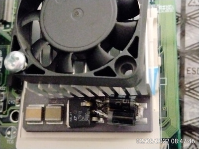
I seem to have some SR560 diodes, they are 5A/60V diodes in 5mm package. The caveat is that they are Schottky diodes, meaning that they have a lower Vf than regular junction diodes. According to the datasheet, they will have a voltage drop of around 0.4-0.45V at 3-4A, so I would have to put 2 of them in series to achieve the required voltage drop. http://eicsemi.com/datasheet/SR520_6.pdf fig.3

I/O, I/O,
It's off to disk I go,
With a bit and a byte
And a read and a write,
I/O, I/O

Reply 21 of 30, by stamasd

User metadata
Rank l33t
Rank
l33t

So I made the mod on the one PODP5V83 I had which didn't have a heatsink. I used two 5A Schottky diodes in series, because I measured them and under 3A load the Vf was around 0.51V for each. It's not the prettiest soldering job I ever did but it's solid and it does the trick. I have measured the voltage the CPU receives, and idle in DOS it's 4.02V, and under load while being benchmarked around 3.96-3.98V. That makes sense because the diodes' Vf increades slightly at higher currents. With that 4x4cm HSF attached on top with thermal tape, it gets warm but not overly so (not uncomfortable to touch). And it's very stable at 100MHz (40x2.5) in all games and benchmarks.

Attachments

  • 2.jpg
    Filename
    2.jpg
    File size
    246.93 KiB
    Views
    426 views
    File license
    Fair use/fair dealing exception

I/O, I/O,
It's off to disk I go,
With a bit and a byte
And a read and a write,
I/O, I/O

Reply 22 of 30, by Tetrium

User metadata
Rank l33t++
Rank
l33t++
stamasd wrote on 2022-02-02, 14:01:

So I made the mod on the one PODP5V83 I had which didn't have a heatsink. I used two 5A Schottky diodes in series, because I measured them and under 3A load the Vf was around 0.51V for each. It's not the prettiest soldering job I ever did but it's solid and it does the trick. I have measured the voltage the CPU receives, and idle in DOS it's 4.02V, and under load while being benchmarked around 3.96-3.98V. That makes sense because the diodes' Vf increades slightly at higher currents. With that 4x4cm HSF attached on top with thermal tape, it gets warm but not overly so (not uncomfortable to touch). And it's very stable at 100MHz (40x2.5) in all games and benchmarks.

Very nice! I really like how the voltage is only slightly higher and you still achieve the intended oveclock 😀

Btw I opted to not include the link to the solutions thread in my OP because it's all on the 1st page anyway.

Whats missing in your collections?
My retro rigs (old topic)
Interesting Vogons threads (links to Vogonswiki)
Report spammers here!

Reply 24 of 30, by feipoa

User metadata
Rank l33t++
Rank
l33t++

Going off of memory only, I recall the POD’s onboard VRM being a fixed voltage regulator (3.45 V), that is, the voltage is not set by external resistors.

Plan your life wisely, you'll be dead before you know it.

Reply 25 of 30, by stamasd

User metadata
Rank l33t
Rank
l33t
maxtherabbit wrote on 2022-02-03, 04:36:

why is this better than the original proposed solution of adding resistance to the feedback of the original regulator?

Apparently you hit a limit that way that doesn't allow you to raise the voltage above 3.7V or so. And in this particular CPU, 3.7V is not enough to make a difference.

feipoa wrote on 2022-02-03, 05:46:

Going off of memory only, I recall the POD’s onboard VRM being a fixed voltage regulator (3.45 V), that is, the voltage is not set by external resistors.

3.5V, but you can get around that to a certain extent. I mean, YOU did the mod and posted the results. 😁 Modifying the POD83's voltage regulator for overclocking

Speaking of which, do you recall what was the long-term stability of that chip at 4V?

I/O, I/O,
It's off to disk I go,
With a bit and a byte
And a read and a write,
I/O, I/O

Reply 26 of 30, by snufkin

User metadata
Rank Oldbie
Rank
Oldbie

I think it was particularly this post you made that helped clear things up: Re: Modifying the POD83's voltage regulator for overclocking
You found that all the components are capacitors, so the resistance stamasd measured from Vout to GND (420 ohms) would be the internal resistors of the fixed output regulator, in parallel with the CPU.
You also found that adding 30 ohms to the regulator between pin 1 and Ground raised the output voltage from 3.5V to 3.73V, and that the regulator seems to start current limiting if you try any higher outputs (current must be going up faster than the voltage across the regulator is dropping).

Using Stamasd's formula for a standard LT108x 3 pin regulator of Vout=1.25*(1+Rb/Ra), then if I've got my maths right I think your measurement implies that the internal resistors are Ra=163 ohm (that's Vout on pin 2 to internal Vadj) and Rb=293 ohm (internal Vadj to pin 1). Which then implies that the 456 ohm measured from Vout to Groud would be 420 ohms (Ra+Rb) in parallel with the CPU, which I think makes the CPU DC resistance around 5k. No idea if that sounds right or not.

Reply 27 of 30, by feipoa

User metadata
Rank l33t++
Rank
l33t++
snufkin wrote on 2022-02-03, 12:18:

I think it was particularly this post you made that helped clear things up: Re: Modifying the POD83's voltage regulator for overclocking
You found that all the components are capacitors, so the resistance stamasd measured from Vout to GND (420 ohms) would be the internal resistors of the fixed output regulator, in parallel with the CPU.
You also found that adding 30 ohms to the regulator between pin 1 and Ground raised the output voltage from 3.5V to 3.73V, and that the regulator seems to start current limiting if you try any higher outputs (current must be going up faster than the voltage across the regulator is dropping).

lol, thanks for the refresher. I'm starting to forget the details of my own posts, and sometimes whole threads. So, now that you mention it, I do recall reaching a 3.7x volt limit and this voltage not being enough for the POD to be stable at 100 MHz. A 3.73 volt limit seems like a very common maximum potential for these regulators when the current is high enough.

Another option is to replace the VRM entirely with another one, but how messy do you want the final product to be? I ultimately decided on the diode mod because it works well enough and can be performed without removing the factory heatsink. I think there's been a nearly 100% success rate with this method, that is, you don't really need to cherry pick your POD83.

Plan your life wisely, you'll be dead before you know it.

Reply 28 of 30, by feipoa

User metadata
Rank l33t++
Rank
l33t++
stamasd wrote on 2022-02-03, 11:54:

Speaking of which, do you recall what was the long-term stability of that chip at 4V?

I used to have a system built around the POD at 4V. I had a GF2 installed and was able to run 3D windows games for hours without crashing. You should check with pshipkov's posts on stability as he tends to go into more depth than me. He has also performed the diode mod.

Plan your life wisely, you'll be dead before you know it.

Reply 29 of 30, by maxtherabbit

User metadata
Rank l33t
Rank
l33t

I have a POD63 that will not run stable at 2.5x33 or at 1x40, leading me to believe the hold up is the BIU, not the core per se. Think a volt mod would do it any good?

Reply 30 of 30, by rmay635703

User metadata
Rank Oldbie
Rank
Oldbie
maxtherabbit wrote on 2022-02-03, 15:09:

I have a POD63 that will not run stable at 2.5x33 or at 1x40, leading me to believe the hold up is the BIU, not the core per se. Think a volt mod would do it any good?

Have you checked your 5 volt PSU rail for noise and steady voltage?

More voltage “should “ bleed over to increased stability to all portions of the chip though admittedly IO voltage affects the BIU more than the core.

Most of my old AT PSUs could be cranked up to output higher voltage on the 5v rail
My experience is that rail is extraordinarily tolerant to over voltage including isa/ide and onboard components

A 2 pronged approach might be warranted if you find a 4.2 volt core voltage is inadequate by itself.

If your motherboard sends 5v unregulated straight to the chip I would test a 5.5v voltage off your PSU, if your PSU sags and is noisy gotta fix that also. If your board does regulate 5v you may need to supply additional power directly to the p24t as they seem to be on the edge of the regulators both on chip and onboard.

Goood Luck