VOGONS


Reply 20 of 85, by retro games 100

User metadata
Rank l33t
Rank
l33t

@DK, when you say "inspected", do you mean that I do a visual check of the yellow bead things? They look OK. Or is there a device that I can use to inspect them, to get some kind of reading from them, to see whether or not one or more of them have failed?

Also, if you look at the photo in the o.p., the yellow thing closest to the headphone port looks different to all of the other yellow things. It's labelled C13 on the Adlib's PCB. I wonder how I can determine if it is working or not?

Maybe in a situation such as this, people simply replace capacitors, not knowing if they worked or not, in the hope that this action will help. Unfortunately in my case, I still haven't got a soldering station, and any knowledge of how to use one.

Reply 22 of 85, by retro games 100

User metadata
Rank l33t
Rank
l33t

Yes, I was wondering how I could use an external PC speaker, to bypass the headphone port and volume knob area, to see if the sound card makes any sound when it is plugged in to a "live" mainboard. Can I just simply temporarily tape both of the exposed PC speaker wires against two solder spots on the back of the sound card? SquallStrife mentions using a probe. I wonder how that works, exactly?

Reply 23 of 85, by h-a-l-9000

User metadata
Rank DOSBox Author
Rank
DOSBox Author

Well if you bridge any pins with these wires this may end up in smoke.

And, oscilloscopes are expensive (except if you buy something really old), and require knowledge and exercise to use.

The tantalum capacitors are not very likely at fault because the capacitor will tend to remove itself from the board when the system manages to power up.

1+1=10

Reply 24 of 85, by Mau1wurf1977

User metadata
Rank l33t++
Rank
l33t++

With the speaker thing, you could connect one cable to the PC case (ground) and then probe various solder points with the other cable. Hopefully you will hear something.

My website with reviews, demos, drivers, tutorials and more...
My YouTube channel

Reply 25 of 85, by retro games 100

User metadata
Rank l33t
Rank
l33t

I wonder if I have spotted something relevant. If you look at the first photo below, I have labelled one of the solder spots with a "1" digit. I don't know why this solder spot is "isolated" and has no associated "data line" on the PCB. Anyway, I turned the sound card over, and looked at what was attached to this solder spot labelled "1". It's a little metal "bar". It can be seen in the second photo below. I have also labelled this metal bar with a "1" digit, but can you see that dark area on the metal bar. It looks burnt. However, it could just be "grime".

Is it possible to attach an external PC speaker to the two solder spots as seen in the first photo - the spot labelled "1", and the spot immediately next to it on the left?

ab476583983e233fbfda1603942087f618ed9c993be60acf58535eaaba25c3dc6g.jpg

2faed2e79ae34dc1024a1f9a925f32810827d865fafcda15419bd35f8faae2c16g.jpg

Reply 27 of 85, by jwt27

User metadata
Rank Oldbie
Rank
Oldbie

That extra pin is probably only used to secure the connector to the circuit board, or to maintain pin-compatibility between mono and stereo connectors or something like that. Nothing to worry about.

If you're going to use a speaker to probe around the board, you'd best use an amplified speaker. An amplifier has a much higher input impedance than a speaker alone, so you won't draw too much current from the card. That means there's a smaller chance you'll accidentally fry the whole card by touching the wrong pin. Plus you can amplify low voltage signals making them easier to hear.

I wouldn't recommend buying an oscilloscope for something as simple as this, unless you're planning on doing more of these repair projects. It would be much cheaper to just replace every single component on the card. Much easier too, since when you do get a 'scope you'll have to know where to measure, what signals to look for, and how to interpret the signals you're measuring.

Something else you could try: Look up the datasheets for all the chips on the card, and for each chip find out which pins are for the supply voltage and what voltage they need to operate. Then plug the card in your PC and measure the actual voltages on these pins.

Reply 28 of 85, by RoyBatty

User metadata
Rank Oldbie
Rank
Oldbie

Yes I agree about the failing tantalums, and that electrolytic is very old and could be dried up/shorting also. Another common failing part is that LM386 op-amp, get another one and socket, and cut the pins on it, desolder them one a time then, put the socket in and the new op-amp (which are common).

Reply 30 of 85, by Jepael

User metadata
Rank Oldbie
Rank
Oldbie

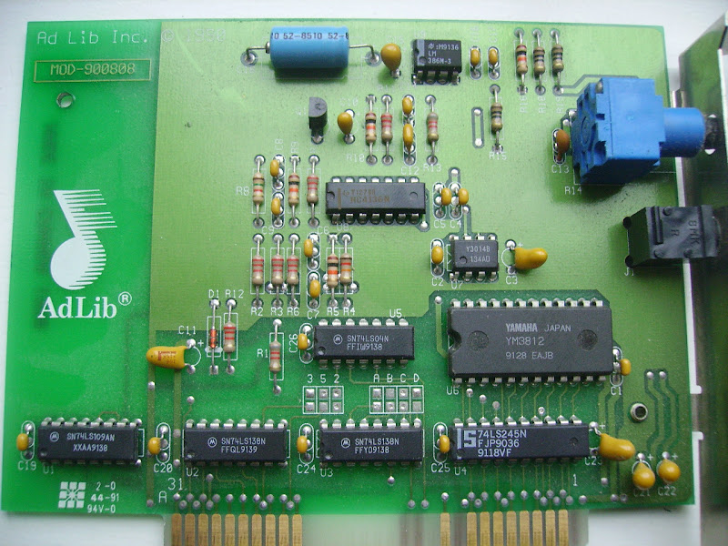
I guess you don't want to mail it to me, but I think I have the tools and knowledge to figure out what is wrong with it. the OPL chip (YM3812) and its DAC (Y3014) are the only components not available anymore, but other components can be replaced.

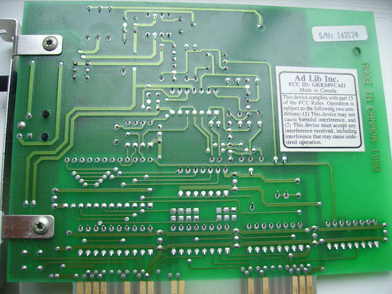
Plus I am eager to get my hands on a real Adlib to find out its component values, even if it is a broken one :)

But first, how do you know it is really dead? Does any sound card with OPL2 (YM3812) chip work in your computer? Are you sure it is the only card that is at IO address 0x388/0x389, so that there is nothing that shares those addresses?

Slow down your PC as much as you can (turbo off, disable caches, etc), and set IO wait states in BIOS setup as high as you can (at least 8-bit wait states need to be at max). The chip needs enough time between IO writes or it won't work, and fast PCs with zero wait states can easily break these timings. Then run a game and see if it works.

If you know how to use DEBUG.EXE from DOS, tell me what "i 388" command returns. It reads the OPL status port. If it returns FF, the card does not answer. If it returns something that ends with a 6, like A6,C6,E6, it means the chip responds to the read command.

Well if it does not respond, I would start poking around with an oscilloscope.
I'd propably check signals in this order:
-Is the YM3812 still held in reset or not (the 7404 inverter)
-Is the 14.318MHz signal from ISA bus correctly divided by the flipflop chip by four so 3.579MHz signal goes to YM3812
-Is there any clocks and data on YM3812 digital audio output to DAC
-Are ISA Bus read/write signals reaching YM3812 RD/WR signals
-Is the address correctly decoded so there is activity on YM3812 CS signal

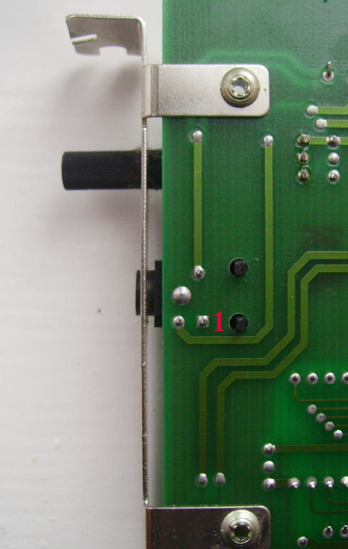
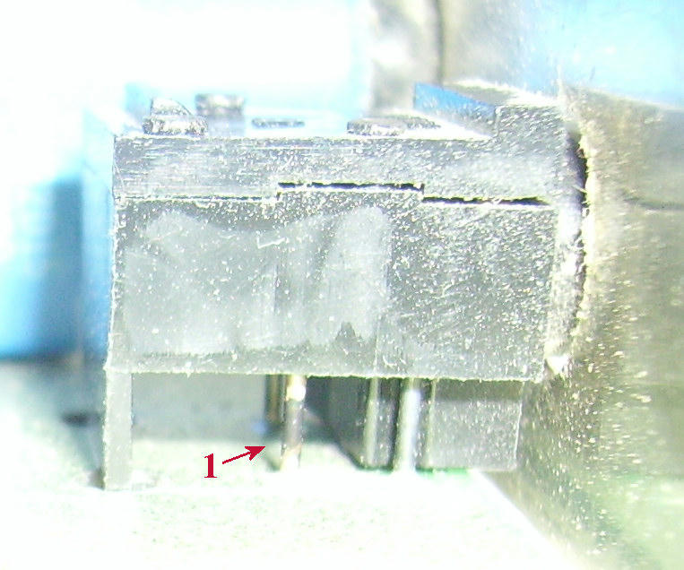
if those look OK, then I'd check the Y3014 DAC, and its associated operational amplifier (usually markings scratched off). In theory, if I could determine from your pictures what leg of the op-amp has the buffered audio output, you could try connecting a small headphone there, or line-in of an amplifier. If there is audio, then the problem is in the LM386 speaker amplifier, or it's muting circuit (the single transistor on board), or it's volume control. In fact, with a multimeter, you could verify you get about 2.5V on Y3014 RB and MP pins. Also 2.5V at the DAC output pin, when there is no audio.

But it's hard to tell someone to debug..

Reply 31 of 85, by retro games 100

User metadata
Rank l33t
Rank
l33t

I am fairly confident that the Adlib card is defective in some way, because I removed this "silent" Adlib card from the mobo, and replaced it with a second identical 1990 Adlib card, and that worked OK in my 386 motherboard. I tried the DOS debug.exe command on the working Adlib card, and also on the "silent" Adlib card, and both cards produced identical results -

C:\debug.exe
- i 388
06

Also, games can "see" the "silent" Adlib card if I select Adlib for music, and then play the game. (However, I hear no sound.)

I would like to mail the card to you, but the only thing is that I'd like it returned please, even if it's broken, because one day someone (perhaps me, although unlikely!) might be able to solve this mystery. But I can pay for all shipping costs both ways, and all PayPal fees, and I can pay you some money to simply have a look at it.

Regarding the "non-replaceable" YM3812 and Y3014 chips. If, after all analysis on the card has been exhausted, it is possible that I can provide an old SoundBlaster card, in order to "cannabalise" these required components. What old sound card has the Y3014 chip? Can this chip be found on an old Sound Blaster?

Reply 32 of 85, by Jepael

User metadata
Rank Oldbie
Rank
Oldbie

Based on what you say, I am also confident that the PC and ISA interface are OK because another card works. And you can read the 06 back which is good. And it seems games can also read write YM3812 registers if they can control it enough to auto-detect it is present.

Yes another (broken) sound card with YM3812 and Y3014B chips can be used. Sound Blasters have these, some models even have two of each because they support stereo FM. The Y3014B is an accompanying DAC chip for converting the digital YM3812 audio to analog, so all sound cards with YM3812 chip shall have Y3014B chip or compatible near it. The Y3014B is also used with other Yamaha chips as well, so it can be found elsewhere too.

I could instruct you to measure some signals or poke a headphone speaker to further narrow down the problem, but you will also have to read a bit of component datasheets to know at least which chip is which and how their pins are numbered and named. Perhaps even post photos of both sides of your card.

Does your multimeter have frequency measurement ability?

Reply 33 of 85, by retro games 100

User metadata
Rank l33t
Rank
l33t

Yes I'd be happy to measure some signals, and also to test the Adlib card with a speaker. BTW, Vogons user jwt27 recommends using an amplified speaker. I wonder, what kind of amplified speaker could I use? I have a pair of multimedia speakers - could I use those?

I can take a photo of both sides of the Adlib card tomorrow, when the natural sunlight is better. My camera produces poor images in artificial light.

Regarding my multimeter, there's a photo of it here (Vogons webpage), about 60% down the page. It's a typical SkyTronics unit. I am ignorant about MMs, and so I don't know if it has frequency measurement ability, or not.

Reply 34 of 85, by retro games 100

User metadata
Rank l33t
Rank
l33t

I managed to get some photos done of the card. I had to tilt the camera a little bit, to get some light in to the camera's lense, so that the camera's flash didn't go off, and spoil the photo.

adlib1.JPG
adlib2.JPG

Reply 35 of 85, by RoyBatty

User metadata
Rank Oldbie
Rank
Oldbie

The Ti chip next to C5, the markings are discolored and almost charred looking, they should be white. This may indicate that that chip is baked. I can't quite read the numbers on it, is it a 4136N ? If so, that is a quad operational amplifier, and is also prone to failure. If you do replace it, try to get one of the same vintage or they will sound different, as they change the designs of the chips regularly. Also stay away from ECG and similar replacements, get the real thing.

Reply 36 of 85, by retro games 100

User metadata
Rank l33t
Rank
l33t

I have a feeling that the "T1" chip's appearance is normal. If I look at my working back up replacement Adlib card, it looks roughly the same - that is, the text on it is not white. BTW, the labelling on the chip is -

T127BB
RC4136N

Reply 38 of 85, by retro games 100

User metadata
Rank l33t
Rank
l33t

As a temporary measure, I have spotted a YM3812 based MediaVision Thunderboard card on ebay, but the seller won't ship outside the US. Is any US resident willing to forward it on to me, please? I'll pay a reasonable "admin charge" for doing this, via PayPal. The item number is 260912589916. Thanks a lot.

Reply 39 of 85, by RoyBatty

User metadata
Rank Oldbie
Rank
Oldbie

Yeah not all marking are white, which is why I said "may" =] Still though from working on audio electronics for ~18 years now, 4136 is common failure. I was just mentioning to try and track down the problem.