VOGONS


PS/2 to Serial Mouse protocol converter

Topic actions

Reply 40 of 125, by feipoa

User metadata
Rank l33t++
Rank
l33t++

Whoops! I somehow missed the ST232CN information, although it was provided in the png schematic as well as earlier in this thread. So I will be using MAX232CPE.

Yes, I took note of the polarity. Unfortunately, I only had 2 tanatlum 1 uF caps in my bin, so I'll be using recycled 1 uF electrolytic caps.

One more question, is there any value in having C5? It is placed in parallel with the 4.7 uF cap, which would make the equivalent combination 4.8 uF.

Plan your life wisely, you'll be dead before you know it.
Reply 41 of 125, by sklawz

User metadata
Rank Member
Rank
Member

hi

feipoa wrote:

Whoops! I somehow missed the ST232CN information, although it was provided in the png schematic as well as earlier in this thread. So I will be using MAX232CPE.

Yes, I took note of the polarity. Unfortunately, I only had 2 tanatlum 1 uF caps in my bin, so I'll be using recycled 1 uF electrolytic caps.

One more question, is there any value in having C5? It is placed in parallel with the 4.7 uF cap, which would make the equivalent combination 4.8 uF.

C5 100n is supposed to be placed near the ST232CN.
You may also place another 100n near the PIC16F628A.
You may place the 4.7uF closer to the power inlet.

Here is some general advice about capacitors:
http://www.seattlerobotics.org/encoder/jun97/basics.html

I am not sure tantalum bead capacitors are a good choice but if they are then I seem to think they should not be used at over 1/2 their rated voltage specification. You may need to look into that and take some measurements.

Bye-bye

EDIT: For useful working voltage range of tantalum capacitors google search: tantalum voltage derating

Reply 42 of 125, by feipoa

User metadata
Rank l33t++
Rank
l33t++

I'm not too concerned about the Tantalum caps. The supply is 5 V. Most through-hole Tantalum caps in the 0.1 - 1.0 uF range are rated for at least 35 V, as mine are.

Thank you for the article on the bypass capacitors, it was a nice review.

sklawz wrote:

C5 100n is supposed to be placed near the ST232CN.

On your breadboard image, you have C5 placed next to the 4.7 uF cap.

Plan your life wisely, you'll be dead before you know it.

Reply 43 of 125, by sklawz

User metadata
Rank Member
Rank
Member

hi

feipoa wrote:

I'm not too concerned about the Tantalum caps. The supply is 5 V. Most through-hole Tantalum caps in the 0.1 - 1.0 uF range are rated for at least 35 V, as mine are.

We can assume that the potential between some on the ST232CN pins is 10V DC since it generates +/- 10V. Your capacitors should be okay but I have not measured anything.

feipoa wrote:

Thank you for the article on the bypass capacitors, it was a nice review.

sklawz wrote:

C5 100n is supposed to be placed near the ST232CN.

On your breadboard image, you have C5 placed next to the 4.7 uF cap.

It's possible that neither are needed but I cannot account for every possible PSU out there. My own supply was well regulated but those of others may not. It's best to use them in a working device.

Bye-bye

Reply 44 of 125, by keropi

User metadata
Rank l33t++
Rank
l33t++

sklawz did you ever made that stripboard layout you mentioned earlier?

🎵 🎧 PCMIDI MPU , OrpheusII , Action Rewind , Megacard and 🎶GoldLib soundcard website

Reply 45 of 125, by sklawz

User metadata
Rank Member
Rank
Member

lo

keropi wrote:

sklawz did you ever made that stripboard layout you mentioned earlier?

I didn't progress with that because the material cost at CPC was more than I was happy to spend on this project. I packed up what was on the breadboard and put the parts away. I got an RKP28SB at christmas and that has been assembled and now demands my attention.

I may get back to it later using spare parts and ebay rather than CPC but anyone else is free to complete this in the meantime, in fact it's encouraged.

CYA! 😀

Reply 46 of 125, by SquallStrife

User metadata
Rank l33t
Rank
l33t

If we can get enough people onboard, it may be economical to have a basic PCB knocked up.

If the circuit can be squeezed in to a 5x5cm board, we can get 10 for under $20 delivered from "ITead" http://imall.iteadstudio.com/open-pcb/pcb-pro … m120418001.html

VogonsDrivers.com | Link | News Thread

Reply 47 of 125, by feipoa

User metadata
Rank l33t++
Rank
l33t++

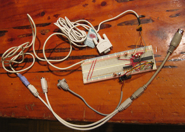
I already have mine assembled on the breadboard and have programmed the PIC. I decided to keep this prototype external and am using a keyboard splitter to provide 5V and ground. If everything works out well with the mouse tracking quality, I'll probably slap it on a solderboard, like I did in this thread for another device, Cyrix MII-433GP Build
Then find a proper enclosure for it.

There are so few components, it shouldn't take more than an hour to wire it up to a solderboard. I was thinking to make one external device (using akeyboard splitter) and one internal device (using motherboard's serial header and floppy power connector).

I'm waiting on some free time to test out the breadboard prototype...

Attachments

Plan your life wisely, you'll be dead before you know it.

Reply 48 of 125, by feipoa

User metadata
Rank l33t++
Rank
l33t++

sklawz, do placing on any of the 4 jumpers require a reset of power, or can they be jumpered on the fly and still have the intended functionality?

Plan your life wisely, you'll be dead before you know it.

Reply 49 of 125, by sklawz

User metadata
Rank Member
Rank
Member

Good day

feipoa wrote:

sklawz, do placing on any of the 4 jumpers require a reset of power, or can they be jumpered on the fly and still have the intended functionality?

The algorithm jumper can be changed on the fly. The algorithm adjusts automatically.

The other jumpers are only inspected during the PS/2 mouse initialisation. For those to be read you must unload and reload mouse.com.

Bye

Reply 50 of 125, by sklawz

User metadata
Rank Member
Rank
Member

hi

SquallStrife wrote:

If we can get enough people onboard, it may be economical to have a basic PCB knocked up.

If the circuit can be squeezed in to a 5x5cm board, we can get 10 for under $20 delivered from "ITead" http://imall.iteadstudio.com/open-pcb/pcb-pro … m120418001.html

It should be possible to fit into a confined space using surface mount components.

The biggest component though, would be a 10-pin serial header to connect to an internal motherboard header. This is quite large in comparison to other components. I looked at crimp pins on CPC to gauge the cost of creating jumper leads but the crimp tooling is extortionate in price and pins only available in bulk. A viable solution to this could be a 3-pin header and then sourcing `dupont' jumper leads from china on ebay.

Basically, there is thought required in the design and material selection for this project.

Bye-bye

EDIT:spelling

Last edited by sklawz on 2013-02-26, 19:08. Edited 1 time in total.

Reply 51 of 125, by feipoa

User metadata
Rank l33t++
Rank
l33t++
sklawz wrote:

The other jumpers are only inspected during the PS/2 mouse initialisation. For those to be read you must unload and reload mouse.com.

What do you mean by unload/relaod mouse.com? Disconnect power, reconnect power? Or disconnect PS/2 mouse from port and reconnect PS/2 mouse from port?

Plan your life wisely, you'll be dead before you know it.

Reply 52 of 125, by sklawz

User metadata
Rank Member
Rank
Member

hi

feipoa wrote:
sklawz wrote:

The other jumpers are only inspected during the PS/2 mouse initialisation. For those to be read you must unload and reload mouse.com.

What do you mean by unload/relaod mouse.com? Disconnect power, reconnect power? Or disconnect PS/2 mouse from port and reconnect PS/2 mouse from port?

Mouse 8.20 in dos:

load:
> MOUSE.COM /C1
unload:
> MOUSE.COM OFF

In windows disabling and enabling the mouse probably works but untested here.

bye.

UPDATE: I just remembered, Mouse 8.20 resets the mouse on every open, for example using EDIT, so options may be selected when the mouse is not operational prior to use.

Reply 53 of 125, by feipoa

User metadata
Rank l33t++
Rank
l33t++

I am using Windows 98SE as my test platform. So rebooting the computer will also work, albiet it will take a little longer?

Plan your life wisely, you'll be dead before you know it.

Reply 54 of 125, by sklawz

User metadata
Rank Member
Rank
Member

Hi

feipoa wrote:

I am using Windows 98SE as my test platform. So rebooting the computer will also work, albiet it will take a little longer?

In windows, device reset will occur whenever windows needs to detect a mouse. It will toggle RTS on the serial port and wait for an 'M' to appear serially on RX.

Power cycling the adapter will work after windows detects a mouse. This is how I tested it. This option may not be practical for you.

Rebooting will definitely work.

In my tests though, I couldn't determine if the PS/2 options actually made a difference and were even supported on my USB+PS/2 mice. They may work better for you.

Cya.

PS. If you attach a logic probe to RA2 you can see it toggle high to low each time the device resets. This way you be sure it is reading the jumpers.

Last edited by sklawz on 2013-02-26, 19:15. Edited 1 time in total.

Reply 55 of 125, by feipoa

User metadata
Rank l33t++
Rank
l33t++
sklawz wrote:

Power cycling the adapter will work after windows detects a mouse. This is how I tested it. This option may not be practical for you.

OK, so with the adapter working and Windows 98SE already booted, I can just remove the 5 V line from the breadboard, change the scaling and resolution jumpers, then put the 5 V line back into the breadboard. The new Scaling/Resolution settings will take effect without having to reboot Windows in this case? If so, maybe I'll add a momentary SPST switch to the 5 V line.

Plan your life wisely, you'll be dead before you know it.

Reply 56 of 125, by sklawz

User metadata
Rank Member
Rank
Member

Hi.

feipoa wrote:
sklawz wrote:

Power cycling the adapter will work after windows detects a mouse. This is how I tested it. This option may not be practical for you.

OK, so with the adapter working and Windows 98SE already booted, I can just remove the 5 V line from the breadboard, change the scaling and resolution jumpers, then put the 5 V line back into the breadboard. The new Scaling/Resolution settings will take effect without having to reboot Windows in this case? If so, maybe I'll add a momentary SPST switch to the 5 V line.

Yes, this is correct.

If device reset is a useful feature to you then !MCLR could be re-enabled, but the reset input would then require a pull-up resistor. To enable !MCLR you will need to re-assemble the source and create a new HEX file. I won't be doing this.

Bye

Reply 57 of 125, by feipoa

User metadata
Rank l33t++
Rank
l33t++

sklawz, thank you for this additional information.

I was unable to get the converter functional. Windows 98 claims there is no mouse. When I connect a standard serial mouse, Win98 has no trouble finding it. I have triple checked all connections, tried two seperate 5 V power sources, programmed two PIC chips, and tried two MAX232 chips. I tried it without any of the optional jumpers enabled.

The MAX232 chip I used calls for 1 uF caps. I only have two 1 uF ceramic caps and plenty of electrolytic caps. I tried using the two 1 uF ceramic caps and 3 electrolytic caps, as well as using five electrolytic caps for the MAX232. The 1 uF electrolytic caps measure 1.45 uF on my LCR meter. The 1 uF cermaic caps measure 0.97 uF. So the cap value is one area of uncertainty.

I connected only the two serial lines noted on the mouse.png.

Unfortunately, I am unable to invest much time into this. Does anyone else plan on assembling this?

Plan your life wisely, you'll be dead before you know it.

Reply 58 of 125, by SquallStrife

User metadata
Rank l33t
Rank
l33t

Electrolytic caps are polarised, maybe you had them in the wrong way?

Page 17 of the datasheet shows the correct orientation - http://datasheets.maximintegrated.com/en/ds/M … X220-MAX249.pdf

I don't mean to insult your intelligence or anything, but I always find that I overlook the simple things when trying to solve problems. 😀

VogonsDrivers.com | Link | News Thread

Reply 59 of 125, by feipoa

User metadata
Rank l33t++
Rank
l33t++
feipoa wrote:

Yes, I took note of the polarity.

The polarity is something I checked several times. The only way something has gone wrong with the polarity is if the spec sheet is wrong. I am hoping someone else will also try this.

Plan your life wisely, you'll be dead before you know it.