VOGONS


First post, by Cloudschatze

User metadata
Rank Oldbie
Rank
Oldbie

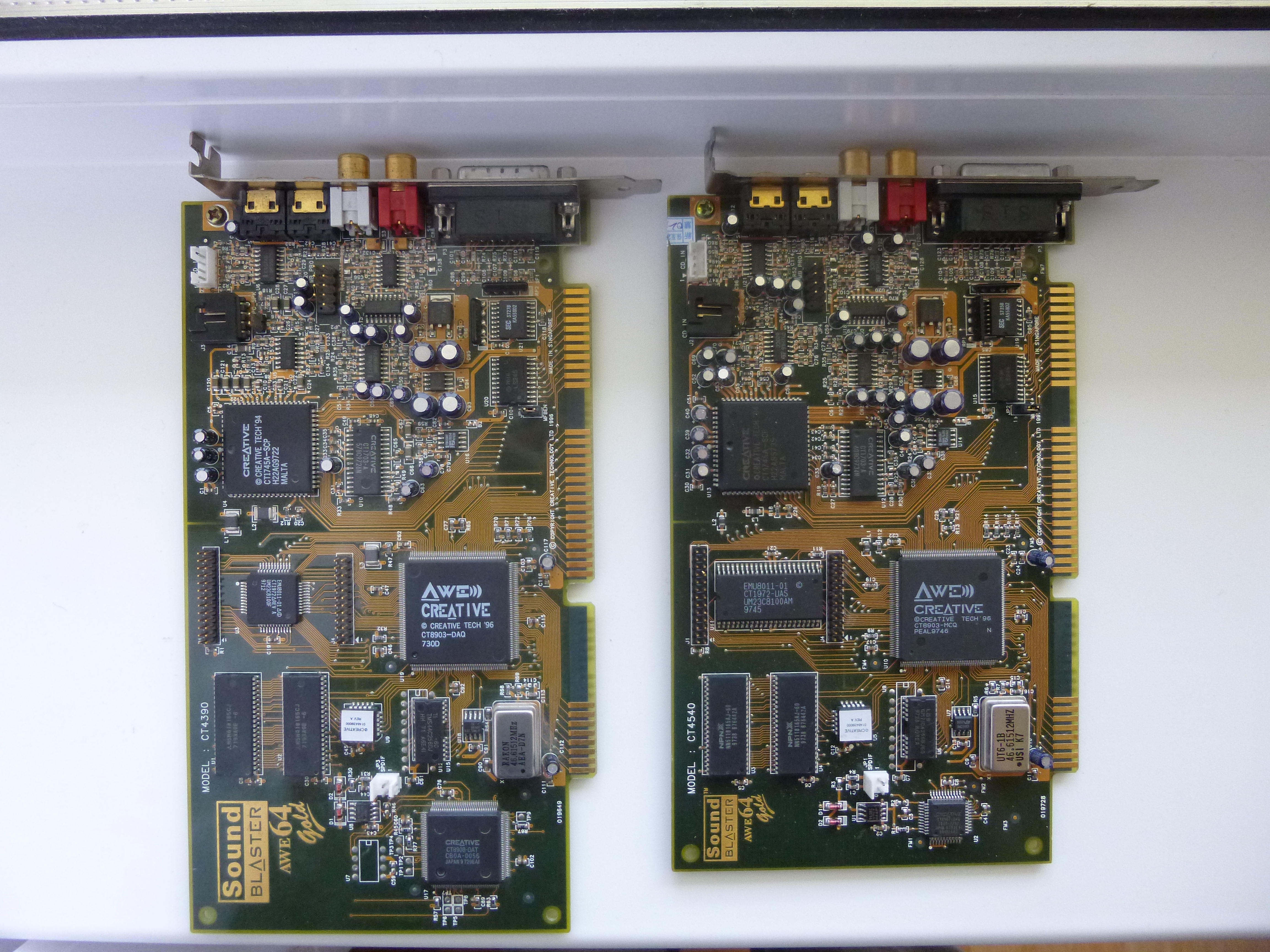
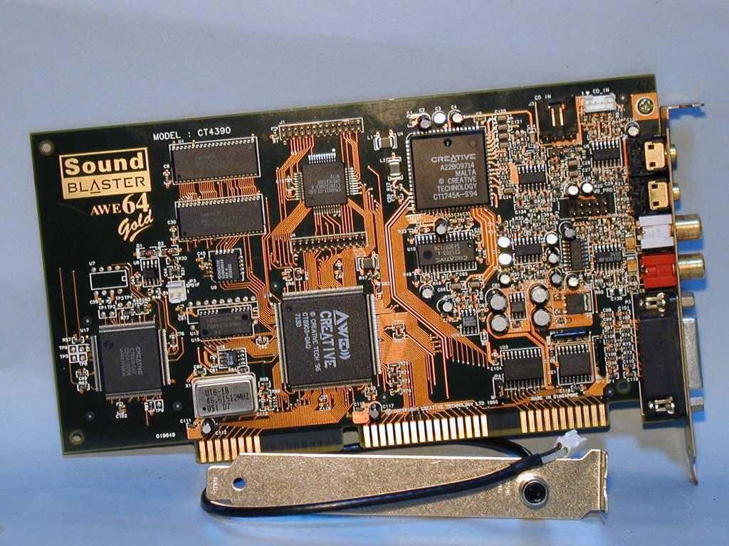
Whilst looking at AWE64 Gold cards the other day, I noticed that the RS-422 chip driving the S/PDIF output can be connected to either of two sources...

ct4390_s.jpg
CT-4390

ct4540_s.jpg
CT-4540

(Click the photos for larger versions.)

The circuits in green are completed by the zero-ohm resistor at R45 and R1, respectively. Moving this resistor to the pads at R46 and R2 would connect the alternate signal instead.

What's the difference, you might wonder? I have no idea. My soldering iron is out-of-commission, so I'm hoping one of the two other guys who bother with S/PDIF might be willing to do some testing... 😉

(Note the yellow point in the red circuit on both cards. This connects the output signal, whatever it is, to the AWE chip. The circuit in green has no such link back to the AWE chip, as far as I've been able to determine.)

Reply 1 of 12, by Stojke

User metadata
Rank l33t
Rank
l33t

Oooh interesting.
I have both cards, but i don't have an SMD soldering kit.

Maybe analyzing the circuit diagram of the Digital SPDIF chip will help? (if there is such a thing freely on the net)

[Edit]

I found info for EMU 8000 while following this discussion:

https://groups.google.com/forum/#!topic/hk.re … ual/YzW2S055B0U
http://www.google.com/patents/US5928342

Note | LLSID | "Big boobs are important!"

Reply 2 of 12, by Cloudschatze

User metadata
Rank Oldbie
Rank
Oldbie
Stojke wrote:

I have both cards, but i don't have an SMD soldering kit.

You wouldn't necessarily need one. A small enough iron tip, used in conjunction with either solder wick, or a sucker, should be enough to remove the zero-ohm resistor. From there, even if the "resistor" wasn't moved to the alternate location, a circuit-trace pen could be used to simply draw the new link.

Maybe analyzing the circuit diagram of the Digital SPDIF chip will help?

Datasheets would be wonderful, but alas, having spent some amount of time looking, I'm still not even sure what, exactly, the CT8907 and CT8908 chips are, or who manufactured them.

Reply 3 of 12, by Stojke

User metadata
Rank l33t
Rank
l33t

Yeah i know, but the soldering gun i have is too inaccurate for this.
I am thinking of asking one of my friends who does mobile phone service to borrow me hi SMD kit.

Maybe you could get answers from Creative 😀

Note | LLSID | "Big boobs are important!"

Reply 5 of 12, by Cloudschatze

User metadata
Rank Oldbie
Rank
Oldbie
j^aws wrote:

It could be an alternative signal path for TOSLink instead of SPDIF - Creative just left the option there and went with the SPDIF bracket...?

No, that wouldn't really require a second signal out of the main chip. TOSLINK refers to the optical connection type, but the data, in this case, is still S/PDIF format. (The existing 2-pin header can actually be used with a TOSLINK connector, if power to drive the optic is supplied from elsewhere.)

I may end up getting around to testing this before anyone else does, but I imagine the output of the alternate signal is likely:

- The same output as the other signal, but at a different bit-resolution or sample rate
or
- Composed of just the EMU8000 output
or
- Composed of just the "digital voice" output
or
- Something else not yet considered 😀

Reply 6 of 12, by Stojke

User metadata
Rank l33t
Rank
l33t

Its for certain its a digital signal processor.
Beacuse OPL is linked to it, allowing effects such as Reverb.

Analyze where the digital out was on AWE 32. It was on the EMU 8000 chip. Meaning this thing might be a newer version of EMU 8000 generator?

Also see on the scheme of the EMU 8000, it has 3 SPDIF outs.
But as you said, a good way to test would be to move the resistor to a new position.

[EDIT]

On the AWE64 classic version the SPDIF out is leading to CT8903-MCQ .
On AWE64 GOLD this chip is CT8903-DAQ, on the newer version its the same as classic - CT8903-MCQ .
So CT8908 has to be some sort of DSP.

Note | LLSID | "Big boobs are important!"

Reply 7 of 12, by Cloudschatze

User metadata
Rank Oldbie
Rank
Oldbie

I think we're getting ahead of ourselves here. 😀 The EMU8000 core is included in the larger CT8903, "AWE" chip. The CT8907 and CT8908 appear to just be some sort of general-purpose digital input chips that appear to at least be multiplexing the EMU8000 and "digital voice" output signals, and may also be providing sample-rate conversion functionality besides.

You gave me the idea to check my CT4500 card, which also has the CT8903, and it turns out that I was wrong about the "yellow dot" in the photos above. This isn't a signal going to the AWE chip, but rather, it's the S/PDIF output from the AWE chip. Using the alternate circuit on either Gold card, as suggested above, is going to result in just the EMU8000/CQM output through the S/PDIF header.

Guess that solves the mystery without having to actually do anything. 😀

Reply 9 of 12, by bristlehog

User metadata
Rank Oldbie
Rank
Oldbie
Stojke wrote:

On AWE64 GOLD this chip is CT8903-DAQ, on the newer version its the same as classic - CT8903-MCQ .
So CT8908 has to be some sort of DSP.

Not sure if you aren't saying the same thing, but my cards correspondingly have CT8903-DAQ and CT8903-MCQ:

Both cards compared

Hardware comparisons and game system requirements: https://technical.city

Reply 11 of 12, by JaNoZ

User metadata
Rank Member
Rank
Member

i am sorry to be a little off the topic but does anyone have schematic of a circuit or a way to attach these awe's spdif output to a modern receiver.?

Reply 12 of 12, by Cuttoon

User metadata
Rank Oldbie
Rank
Oldbie
JaNoZ wrote on 2013-07-20, 07:48:

i am sorry to be a little off the topic but does anyone have schematic of a circuit or a way to attach these awe's spdif output to a modern receiver.?

I came here with the same question. Judging by the photos I found of the real thing, the breakout bracket is just a "dumb" cable and an RCA plug. The "ground" (shield, outer) pole of the thing goes to the pin closer to the edge of the card, designated "0".
- At least that's how I interpret the photo linked to above (thicker cable is usually the shielding) and these instructions:
https://flaterco.com/kb/audio/ISA/index.html#AWE64
If in doubt, get that HT-Omega CA-1 cable and attach it as shown. (The link is broken, but the cable can be found)
Haven't tried it out so far, don't think you can break much with a 1.5 Volt signal, but proceed on you own risk. ;)

I like jumpers.