Some years ago, my boss at work threw away a little 8" LCD tv from Maplins, which I kept. It could take VGA but looked terrible doing it with awkward scaling, but it had a 640 x 480 LCD in it, so I threw away the TV and kept the LCD.
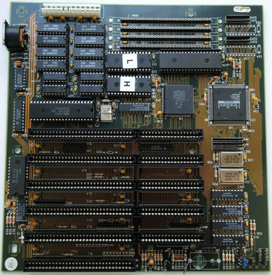
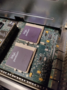
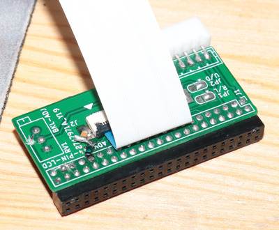
Some months ago I made this PCB for the 44-pin LCD connector that you can find on many industrial PCs and single board computers. Initially I thought it was advantech specific but it seems to be standard across many of the Taiwanese integrators that were making x86 SBCs.
The LCD that I took out of that 8" LCD TV uses a 32-pin flat flex cable with I think 0.5mm pitch pin spacing that's way too small for me to solder, thus this PCB was necessary and it's worked for several other LCD panels but not this little Sharp 8" LCD and I had no idea why. It's been on my 'please fix this at some point' pile for a long time.
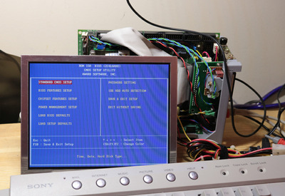
It would work with this board but it would show noise on any details on the screen like in the BIOS screen the red & white text would have some break-up here and there. In Windows any details like the start menu were illegible and when doing the Shut down Windows screen which does the cross-hatch thing, the display would just break entirely on displaying that.
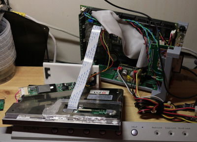
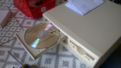
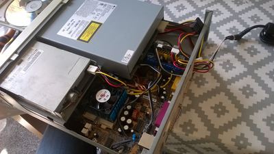
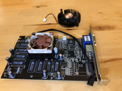
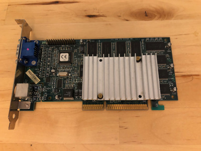
Initially I thought it was down to the BIOS on this Advantech PCA6145 and other SBCs that had wrong details to drive this LCD panel since the LCD worked with its original board and the digital picture frame driver boards, where I'd sourced other 640x480 TFT LCDs from digital picture frames. I'm upcycling them 😀
Going through it all on the oscilloscope looking at signals I noticed that the picture frame boards did drive the screen at a higher frequency and was trying to figure out if there's a way to make the SBC's BIOS match this, but I couldn't see a way to do that. Then I had a read of yyzkevin's experiences with getting a VGA LCD working with custom wiring: https://www.yyzkevin.com/clock-signal/
I am so glad this information is shared, the frequences matched up to what my SBC was putting out at ~25mhz so maybe there's no way to change the frequency. Also the amplitude of my clock signal was all wrong, 8 volts peak to peak?
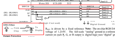
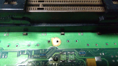
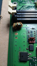
I found that my SBC doesn't implement any filtering on the motherboard for the LCD signals so my PCB should have been doing that. To fix that I cut the trace for the clock signal and started bodging on new parts, to match up what the Chips & Tech CT65550 datasheet specifies for filtering. 220pf capacitor and initially I tried resistors in line, that was bad.
But then I stole this blue filter thing from a scrap PCB's USB data lines and tested again, now the display is 100% working! I need to figure out what this part is called so I can get a fixed PCB version eventually 😀
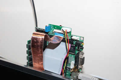
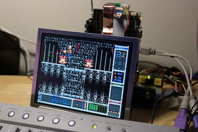
The clock signal looks cleaner on the scope, the display is great now, it even handles the cross-hatch in the Windows shutdown screen, pixel perfect. All it was was just how 'clean' the clock signal is when there are ~20 other signals in total.
This means I can start making something to hold this screen and an SBC at last.
Thanks Kevin for sharing your experiences with LCD troubleshooting 😀