kingcake wrote on 2023-11-26, 20:20:
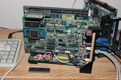
Thermalwrong wrote on 2023-11-26, 14:38:Wow, that board looks like it should be fun to use, with PCI and EISA. Good job catching the bad capacitors before they could do […]
Show full quote
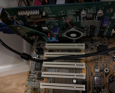
Wow, that board looks like it should be fun to use, with PCI and EISA. Good job catching the bad capacitors before they could do more damage 😀
Also that big regulator looks like it's missing the heatsink. Is that just while fixing it or it's really missing? It looks very similar to the heatsink on my AN430TX Intel board
appiah4 wrote on 2023-11-26, 09:36:
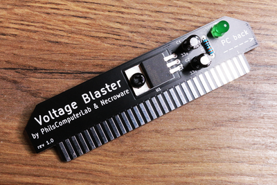
Does it actually work? I have one of these and tried to erase EEPROMs with it, and it did nothing..
Maybe it needs a couple of runs through? If it's a UVC lamp tube it should work.
Looking around I can see that UV sterilizer boxes for phones / small stuff are a thing and they have UVC lamp tubes in too - but no one's buying them so they're super cheap now, £4. I'm getting a UVC lamp type box and a UVC LED that's rechargeable to see how well they perform 😀 I've got a few UV eraseable EPROMs that I've never been able to do anything with.
Don't waste your time with LED based devices. Real UV LEDs are mega expensive. The LEDs in those cheap devices are more purple than UV.
This topic set me off on a tangent to learn about UVC and what EPROMs require to erase. I've tried erasing EPROMs with a window using visible UV torches exposing for ages but that didn't do a thing.
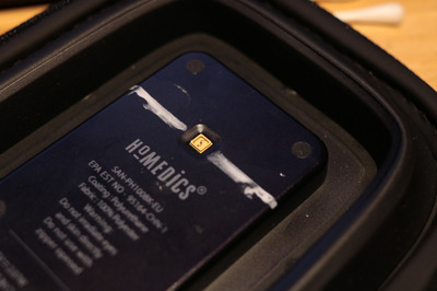
Following these posts I bought a £4 UVC tube based phone steriliser and a £6 Homedics UV Phone Sanitizer which uses LEDs, worth checking out for just a tenner 😀 I have enough UV-erasable EPROMs that I can't use that it's worth doing.
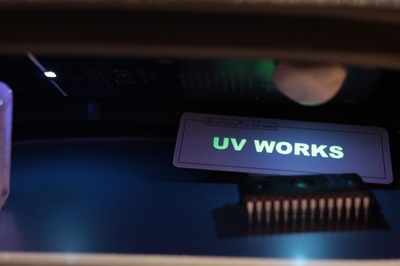
I tested out both at erasing EPROMs and I was surprised at how effective the LED type actually is - the real UVC LEDs can be identified by the gold colour housing. I'll bet this wasn't cheap to manufacture but now no-one's buying consumer sterilisation equipment, this can be had for ridiculously cheap where I'm pretty sure it's being sold below cost price now:
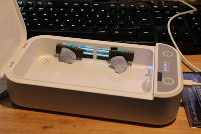
Here's the tube type sanitiser, I modified it so both tubes are on the same side and disabled the speaker which had ridiculous voice prompts, apparently this thing does aromatherapy for phones 🤣. It's built so ridiculously cheaply it doesn't have a lid-open sensor so I can do all the eye & skin damage I want with it.
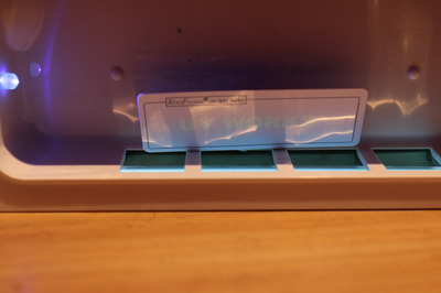
But it came with a UVC test strip and here's the comparison between the two. Not a fair comparison though, the LED sanitiser's power output has been doubled while I don't know how / want to modify the tube sanitiser apart from moving the tubes. The tube sanitiser is probably not indicative of output power with all UVC tube lights, I suspect it's running the tubes at quite low power, they only draw 500ma at 5v. Better tube lamps probably give more output.
To improve the power output on the LED phone sanitiser I followed the instructions here, to boost the power output to around 2x standard. It runs for 30 seconds each time which seems short but it's rather effective - here's what it does now:
Because the LED light is concentrated in one spot it's really perfect for the EPROM window, which is blasted thoroughly enough that the EPROM is successfully blanked in 4 minutes with 8x button presses. For comparison, the UVC tube sanitiser clears the EPROM in 30 minutes quite reliably.
Now all my EPROMs are blank and ready for use 😀