VOGONS


First post, by 133MHz

User metadata
Rank Oldbie
Rank
Oldbie

Hi everyone! I've just bought a non-working Macintosh Plus 1Mb from a fellow collector at a local retro computing forum, described as having a typical analog board failure. I've got a little bit of experience repairing these, the usual cold solder joints, bad capacitors and shorted flyback transformers, but this one turned out a bit more involved.

First the back of the case says 220-240VAC input voltage but the analog board is a 630-0102-J (110V non-switchable) and I found a lot of blown components near the power supply primary. Since I live in an NTSC country with 220V mains there's a pretty high chance that the damage was caused by plugging in the machine straight to the wall without a step-down transformer, with quite catastrophic results. I've added a 130V varistor across the AC input after the fuse as a protective measure in case such an accident happens again.

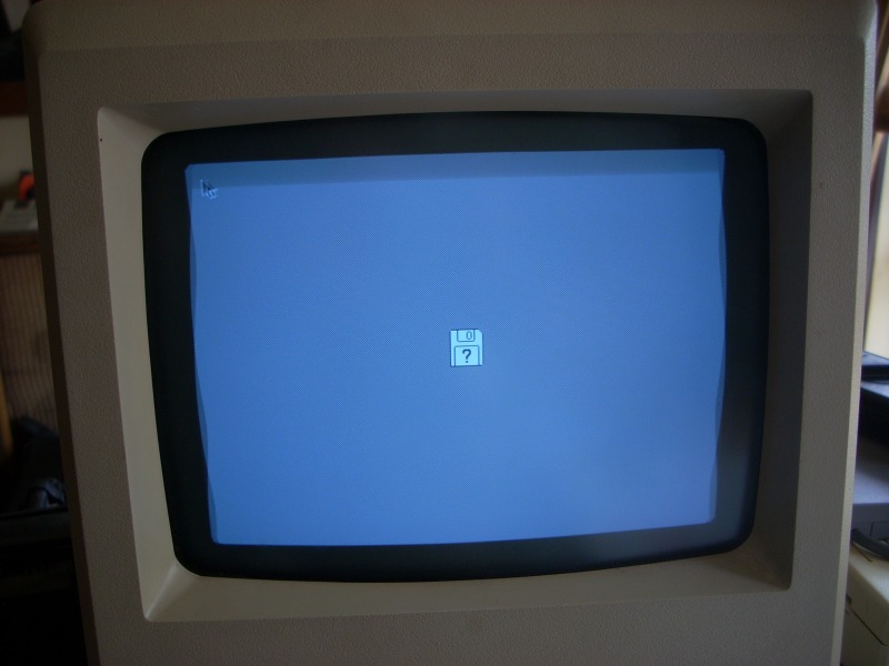
Resistors R46, R47, R49 and R51 were blown open, Q9 (2N3906) and Q11 (2SC2810) were shorted along with a blown line fuse. Replaced all the failed components (subst. Q11 by a BUT12A) and replaced C39, C43 & CR28, CR29, CR30 (subst. with FR157), CR31, C35 & C36 (main filter caps) C1 & C2 for good measure, along with the usual solder reflowing on the conectors. Now if I power up the machine with straight 110VAC it immediately crowbars, even with R56 turned all the way down. If I bring up the voltage slowly with a Variac it will come on with large ripple down the sides of the raster, at about 67VAC input PSU will output 5V and 12.4V and the logic board boots up, but there's no voltage regulation whatsoever. turning R56 does absolutely nothing and if I keep cranking up the Variac output voltages continue to climb until the crowbar fires.

I've tested the resistors around the feedback area along with R56 itself and they seem to be OK. Temporarily substituted optocoupler U3 and SCR Q10 with different but compatible parts with no change whatsoever. The only thing I haven't changed is CR19 (6V2 zener) because I don't have a suitable replacement handy. What else could be causing this problem? Am I overlooking something?
dscn1841.jpg?w=800

http://133FSB.wordpress.com

Reply 1 of 6, by jwt27

User metadata
Rank Oldbie
Rank
Oldbie

I have no experience with these (andnot too much with switching power supplies in general) but I found a schematic/manual here: http://home.earthlink.net/~gamba2/images/plus_analog.PDF

I'd check for a switching signal from U3 first. If there is none, the fault lies somewhere in the feedback circuit. Check for a signal on pin 7 of U1 in that case.
An easy way to test the zener is simply to check for 6.2V across it.

(also how is U1 supposed to monitor the 12V rail properly if it's powered by the 12V rail itself??)

Reply 2 of 6, by Jepael

User metadata
Rank Oldbie
Rank
Oldbie

As long as power supply is large enough for the circuit to work (about 7.7 volts or greater), U1 can compare the divided-down supply voltage to the 6.2 volt reference so the feedback loop tries to control the supply voltage until both op-amp inputs have equal voltage of 6.2 volts (the voltage divider network is adjusted with a trimmer so that 12 volts gets divided down to 6.2 volts).

Reply 3 of 6, by 133MHz

User metadata
Rank Oldbie
Rank
Oldbie

I've pulled the optocoupler and scoped the output of the op-amp driving it, there's a nice rail-to-rail pulse width modulated signal controlled by R56 and also the 6.2V reference is OK so I assume the feedback control circuitry is good and my problem lies on the other side of the optocoupler.

Replaced the optocoupler with a 4N26 and no change, I'm suspicious of Q10 (30V 0.8A fast recovery SCR) but I don't have any of those at hand, just a boring slow TYN412.

EDIT: Stuck Q10 on a protoboard with a LED and found out it's leaky, so I believe I found the problem. Now I gotta wait until I can get a replacement.

http://133FSB.wordpress.com

Reply 4 of 6, by 133MHz

User metadata
Rank Oldbie
Rank
Oldbie

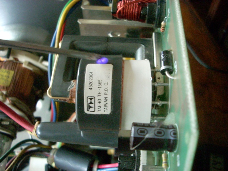
Got a 2N5064 as a replacement for Q10, along with finding that the original optocoupler was also bad and R44 (100Ω) had drifted up to 133Ω. Replaced all three and now R56 does have an effect on the output voltage, but at full line voltage the OCP/OVP continually kicks in even at the lowest setting. Once again slowly bringing up the AC through the variac I can get the same wavy raster as before, as soon as I get close to normal operating voltages OCP/OVP fires again, but with some careful twiddling I was able to get a stable raster and a successful boot, accompanied by that infamous sizzling sound of frying bacon that is so characteristic of a high voltage leak, and sure enough, using myself as a capacitive return path this happens:
dscn1847.jpg?w=800
It leaks all over the place and a few seconds later we're back into overload. My conclusion is that the flyback is partially shorted, causing it to draw too much current in normal conditions, but at reduced voltage/current it sort of works, enough to produce some raster at least.

It's clear I'll be needing a replacement flyback, but there are a few other things that bug me. With the flyback completely removed the power supply still overloads like before, even when putting some dummy load on the +12VF line which makes me believe there's still something wrong with the feedback/regulation circuits. I remember a while ago when repairing a friend's Mac Plus (international version) that the PSU would run fine without the flyback, which makes me suspicious that this one doesn't. Another thing is that The Dead Mac Scrolls and the official Apple schematic calls for 1N4001's for CR28 to CR30, while Classic Mac Repair Notes call for 1N493x. Given that the PSU oscillates at tens of kHz the fast recovery diodes make much more sense than simple 1N400x's.

While I won't be able to do much until I can get my hands on a replacement flyback transformer, I still think that something's not quite right with the power supply, maybe the choice of replacement opto/SCR could have to do with it, or it could be something else I'm overlooking.

http://133FSB.wordpress.com

Reply 6 of 6, by 133MHz

User metadata
Rank Oldbie
Rank
Oldbie

Did a cursory ESR check on all of the big caps and they were fine, replaced C1, C2, C35, C36, C9 and C43 anyway. Doesn't mean the rest couldn't have reduced capacity and/or leaks, and I'll be replacing them anyway, but in this case the ripple was caused by reduced line voltage. I was able to get a ripple-free raster for a bit but then the flyback started sizzling and leaking HV.

http://133FSB.wordpress.com