VOGONS


First post, by Dropcik

User metadata
Rank Newbie
Rank
Newbie

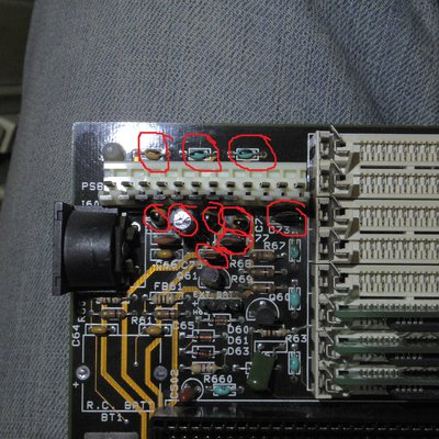
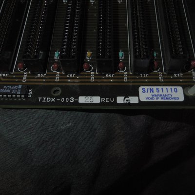
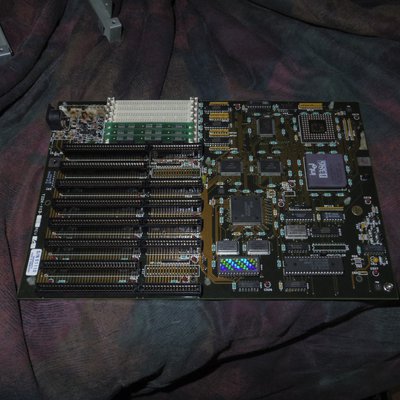
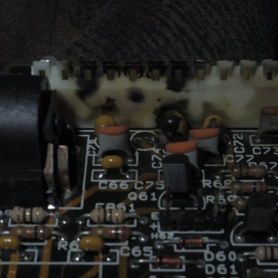
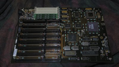
I have an 386 motherboard from early 1990, with no indication from what vender its made by.The capacitor blew when it was on for 5 minuets. I have desoldered the capacitor and cleaned it up a little. It still powered on when it was blown, but I let it sit for a year and now it wont post. So if anyone can point me towards some information on the motherboard or have any idea what specs the tantalum capacitor was it would be greatly appreciated.

Attachments

  • _IGP4010.JPG
    Filename
    _IGP4010.JPG
    File size
    1.26 MiB
    Views
    1704 views
    File license
    Fair use/fair dealing exception
  • _IGP4011.JPG
    Filename
    _IGP4011.JPG
    File size
    1.48 MiB
    Views
    1704 views
    File license
    Fair use/fair dealing exception
  • _IGP4009.JPG
    Filename
    _IGP4009.JPG
    File size
    1.08 MiB
    Views
    1704 views
    File license
    Fair use/fair dealing exception
  • _IGP4005.JPG
    Filename
    _IGP4005.JPG
    File size
    3.44 MiB
    Views
    1704 views
    File comment
    High Quality Motherboard
    File license
    Fair use/fair dealing exception

Ayy LMAO

Reply 1 of 19, by HighTreason

User metadata
Rank Oldbie
Rank
Oldbie

Probably like 100µF 50V, possibly less but it wouldn't likely hurt to put one that size in. Could always go for a 220µF in that footprint just to be safe - you can usually install capacitors that are of higher value when they are for filtering out noise from the power supply like that one would be, the designer will often just use the smallest ones they can get away with (or omit them entirely where possible) to save cost and not necessarily that it's the ideal value.

The problem though is more likely that another tantalum has gone short.

My Youtube - My Let's Plays - SoundCloud - My FTP (Drivers and more)

Reply 4 of 19, by Dropcik

User metadata
Rank Newbie
Rank
Newbie
HighTreason wrote:

Probably like 100µF 50V, possibly less but it wouldn't likely hurt to put one that size in. Could always go for a 220µF in that footprint just to be safe - you can usually install capacitors that are of higher value when they are for filtering out noise from the power supply like that one would be, the designer will often just use the smallest ones they can get away with (or omit them entirely where possible) to save cost and not necessarily that it's the ideal value.

The problem though is more likely that another tantalum has gone short.

Can I use a 25v 100uf capacitor? I saw online some guy used a 25v 4.7uf cap in place of a 50v 4.7uf cap to fix some arcade machine. And its the only one I have found that is 100uf. I traced the printout bat to the psu and its for the 12 volt line for the isa slots. So would the 25 volt capacitor work?

Ayy LMAO

Reply 5 of 19, by smeezekitty

User metadata
Rank Oldbie
Rank
Oldbie
Dropcik wrote:
HighTreason wrote:

Probably like 100µF 50V, possibly less but it wouldn't likely hurt to put one that size in. Could always go for a 220µF in that footprint just to be safe - you can usually install capacitors that are of higher value when they are for filtering out noise from the power supply like that one would be, the designer will often just use the smallest ones they can get away with (or omit them entirely where possible) to save cost and not necessarily that it's the ideal value.

The problem though is more likely that another tantalum has gone short.

Can I use a 25v 100uf capacitor? I saw online some guy used a 25v 4.7uf cap in place of a 50v 4.7uf cap to fix some arcade machine. And its the only one I have found that is 100uf. I traced the printout bat to the psu and its for the 12 volt line for the isa slots. So would the 25 volt capacitor work?

Although it is generally not good practice to replace a capacitor with one of a lower voltage rating, there shouldn't be more than 25 volts anywhere on the board so it should be okay.

Reply 6 of 19, by HighTreason

User metadata
Rank Oldbie
Rank
Oldbie

Yeah, if it's on the 12V rail you should be fine with 25V unless the other pin is tied to the -12V rail.

I always spec 50V as a minimum in PCs personally because I like to grossly over-engineer everything and assume the worst may happen at some point. A lot of the ones I've replaced have been 6.3V, 16V and 25V rated. As long as the capacitor is rated for a higher voltage than it will ever be connected to you're generally good to go, it just might not last so long (such as 5-7 years instead of 10-15) before wearing out.

For power circuits the farad rating (Usually µF of pF) should be equal to or slightly greater than the original... You need more precise values when working on signal lines though, as an example, if you were to change the values on a sound card the capacitors would be used to filter things out of the audio signal and you'd end up with more treble and noise with smaller ones and more bass with larger ones.

My Youtube - My Let's Plays - SoundCloud - My FTP (Drivers and more)

Reply 8 of 19, by Dropcik

User metadata
Rank Newbie
Rank
Newbie

Well I replaced it and sill nothing happened. The board shows no other signs of damage, other than the scorch marks left from the previous capacitor. Any other ideas?

Ayy LMAO

Reply 9 of 19, by Anonymous Coward

User metadata
Rank l33t
Rank
l33t

Is that BIOS original? I don't see too many 386s with holographic stickers on the BIOS chip.

You should use a multimeter and check all the tantalum capacitors for closed circuits.

"Will the highways on the internets become more few?" -Gee Dubya
V'Ger XT|Upgraded AT|Ultimate 386|Super VL/EISA 486|SMP VL/EISA Pentium

Reply 10 of 19, by Dropcik

User metadata
Rank Newbie
Rank
Newbie
Anonymous Coward wrote:

Is that BIOS original? I don't see too many 386s with holographic stickers on the BIOS chip.

You should use a multimeter and check all the tantalum capacitors for closed circuits.

yea, it looks to be a standard award 386 isa bios

Ayy LMAO

Reply 11 of 19, by popper

User metadata
Rank Newbie
Rank
Newbie

To check a capacitor you can use a multimeter - the ohmmeter that is built in - and look at the figures it shows. AFAIR first you should see small, then rising numbers (resistance), what indicates it should work (otherwise it's already dead). There is a problem to figure out if the capacitor is still in its intended state, because it is mostly still mounted on a circuit board and other components distort your measurement. To get sure of it, i think there is no other way then to isolate the capacitor, which means you have to get it of the board - and no one is willing to do that for approximately 354 of them on one single motherboard.
Electrolytic ones rise their 'cap' when they are dry and end of life, tantalum ones do not show any signs (i haven't seen a single bit of a sign on them, even when they blew into pieces within the next second...) and thus are more 'tricky'.
I am still searching for a method to find dead capacitors, because even if a tantalum one is replaced (and mostly it is easy to find - as your picture shows) i often sit next to a non-working board and have no idea what causes its condition furthermore.

errare humanum est

Reply 12 of 19, by Dropcik

User metadata
Rank Newbie
Rank
Newbie

I'm testing the capacitors right now. All of the blue and yellow-tan ones give me 60 ohms of resistance. The bad ones (gave me no reading at all) were around the psu connector. Should these capacitors be reading 60 ohms or should they be a different value?

Ayy LMAO

Reply 13 of 19, by Dropcik

User metadata
Rank Newbie
Rank
Newbie

Here is all of the capacitors that were bad. even the one I first replaced 😒 . any capacitor recommendations? Its hard to read the values on these.

Attachments

  • e.jpg
    Filename
    e.jpg
    File size
    1.55 MiB
    Views
    1438 views
    File license
    Fair use/fair dealing exception

Ayy LMAO

Reply 15 of 19, by Dropcik

User metadata
Rank Newbie
Rank
Newbie

Wow, I gave up a long time ago finding this board. It was a pretty low end board so I never really invested a lot of time fixing it. I ended up taking parts off of it for other boards. Thanks for finding out what it was, I could only spend so long looking at pages of black and white motherboard layouts on TH99. The site you linked seems a lot better.

Ayy LMAO

Reply 16 of 19, by Deksor

User metadata
Rank l33t
Rank
l33t

We made this site, based on TH99 😀
Do you still have the ROM ? We're interested to have a dump of it to add it to the page.

Trying to identify old hardware ? Visit The retro web - Project's thread The Retro Web project - a stason.org/TH99 alternative

Reply 18 of 19, by pentiumspeed

User metadata
Rank l33t
Rank
l33t

This is nice board. Looks like someone designed to Intel specs due to caps around each socket.

Cheers,

Great Northern aka Canada.

Reply 19 of 19, by evasive

User metadata
Rank Oldbie
Rank
Oldbie
Dropcik wrote on 2021-05-24, 15:38:

I still have the board. I'll grab it next time I'm at my mom's house. I believe I can do a rom dump using a pci nic.

That would be awesome, thank you.